Single monitor wall mount with gas spring, SolidHand-BGW01W
GTIN: 5907614667634 · SKU: SolidHand-BGW01W
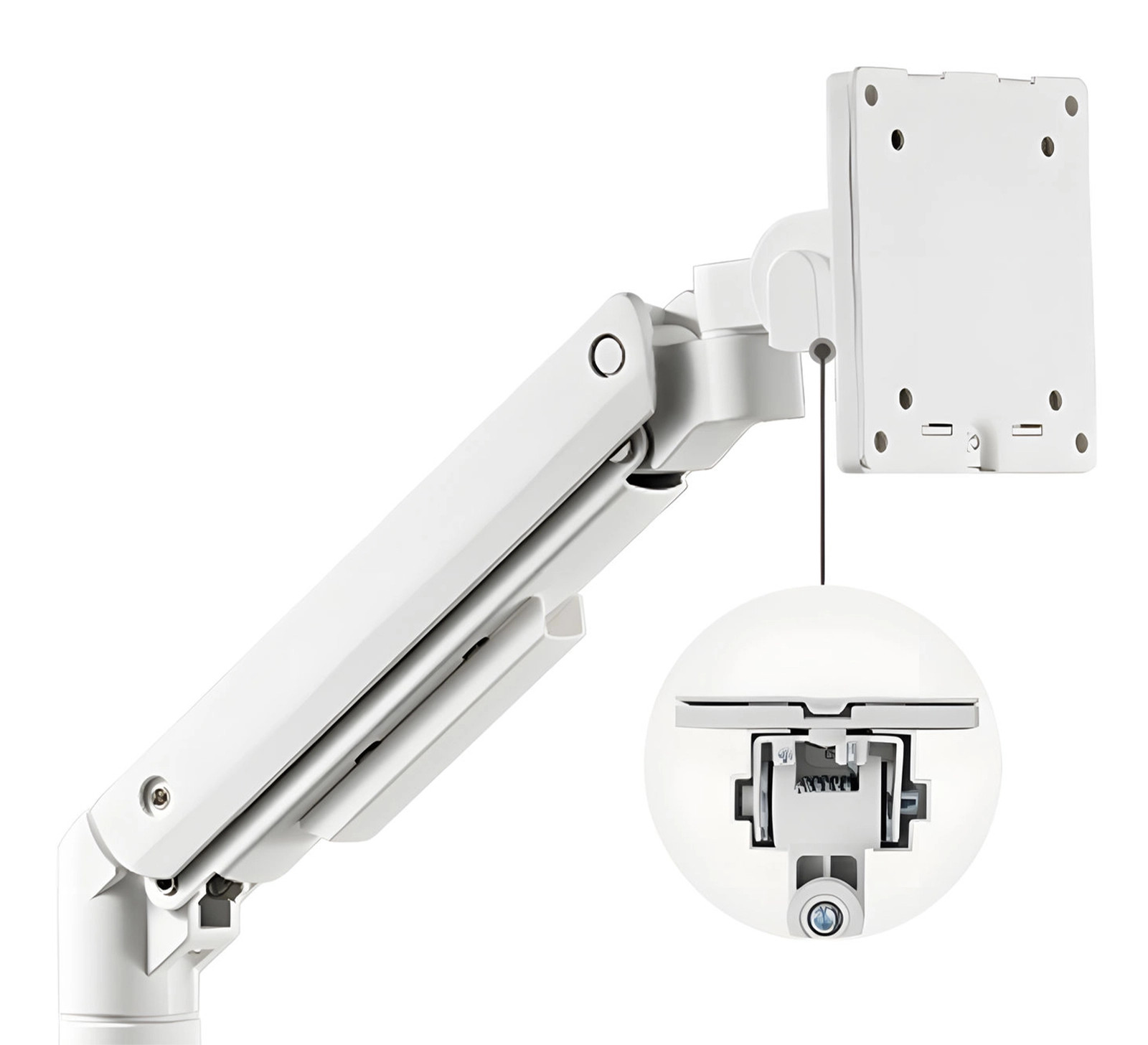
The SolidHand-BGW01W is a white wall mount for a single monitor from 17 to 49 inches weighing 2 to 20 kg. A gas spring counterbalances the screen, so it moves at the touch of a hand and stays where you leave it. The arm folds flat against the wall and extends up to 424 mm, the joints turn ±90° and ±180°, and the head tilts from −20° to +50° and rotates ±180°, so the screen can be set upright. The wall plate is fixed either to a timber stud or to a masonry wall on plugs, and the cables run under covers clipped onto the arm.
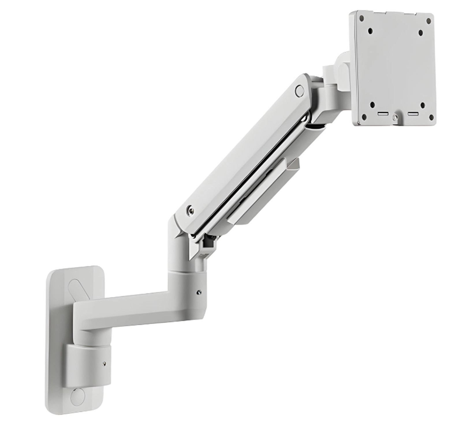
Table of contents
Specification
- Colour: white
- Material: aluminium, steel, plastic
- Surface finish: powder coating
- Number of monitors: 1
- Monitor diagonal: 17–49"
- Monitor weight: 2–20 kg
- VESA standard: 75 × 75 mm, 100 × 100 mm
- Height adjustment: gas spring assisted, travel up to 269 mm
- Arm rotation range: from −90° to +90°
- Monitor rotation range: from −180° to +180°
- Monitor tilt range: from −20° to +50°
- Max. arm reach: 424 mm
- Reach segments: wall plate 40 mm, fixed arm 185 mm, gas spring arm 240–288 mm, head 84 mm
- Installation: wall mounting — timber stud or masonry
- Mount dimensions: 116 × 547 × 480 mm
- Package dimensions: 43 × 20 × 11 cm
- Mount weight: 3.3 kg
- Weight with packaging: 3.74 kg
Kit contents
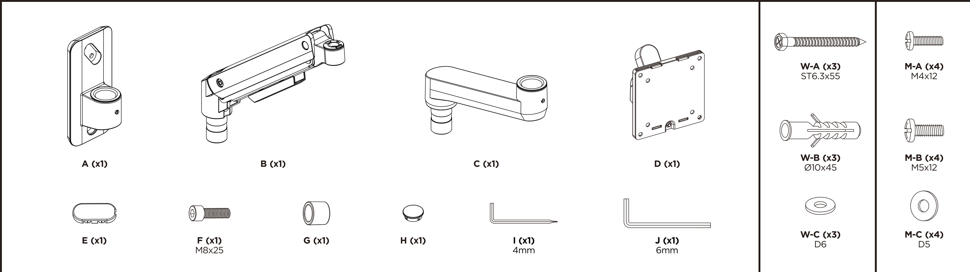
- A — wall plate with hinge block (× 1)
- B — gas spring arm (× 1)
- C — fixed arm (× 1)
- D — VESA head with removable plate D1 (× 1)
- E — side cover cap (× 1), H — round cover cap (× 1)
- F — bolt M8 × 25 mm (× 1), G — spacer sleeve (× 1)
- I — 4 mm Allen key (× 1), J — 6 mm Allen key (× 1)
- W-A — wall screw ST6.3 × 55 mm (× 3), W-B — wall plug Ø10 × 45 mm (× 3), W-C — washer D6 (× 3)
- M-A — monitor screw M4 × 12 mm (× 4), M-B — monitor screw M5 × 12 mm (× 4), M-C — washer D5 (× 4)
Before you start
The installation takes about half an hour. Prepare:
- Read the whole manual before you start and follow the installation steps exactly
- Check that every part from the list above is in the box; if anything is missing or damaged, contact us before you begin
- Both Allen keys are supplied; you additionally need a stud detector, a spirit level, a pencil, a drill and a socket wrench
- A second person to hold the monitor while it is hung on the arm
- A monitor of 17–49" with VESA 75 × 75 or 100 × 100 holes, weighing 2 to 20 kg

The wall must carry the weight of the mount and the monitor together. Using the mount with loads above the stated limit may make it unstable and cause injury.
Installation
Step 1 — Fix the wall plate
The wall plate (A) is fixed in one of two ways, depending on what the wall is made of. Only the fixings differ; the rest of the assembly is identical.
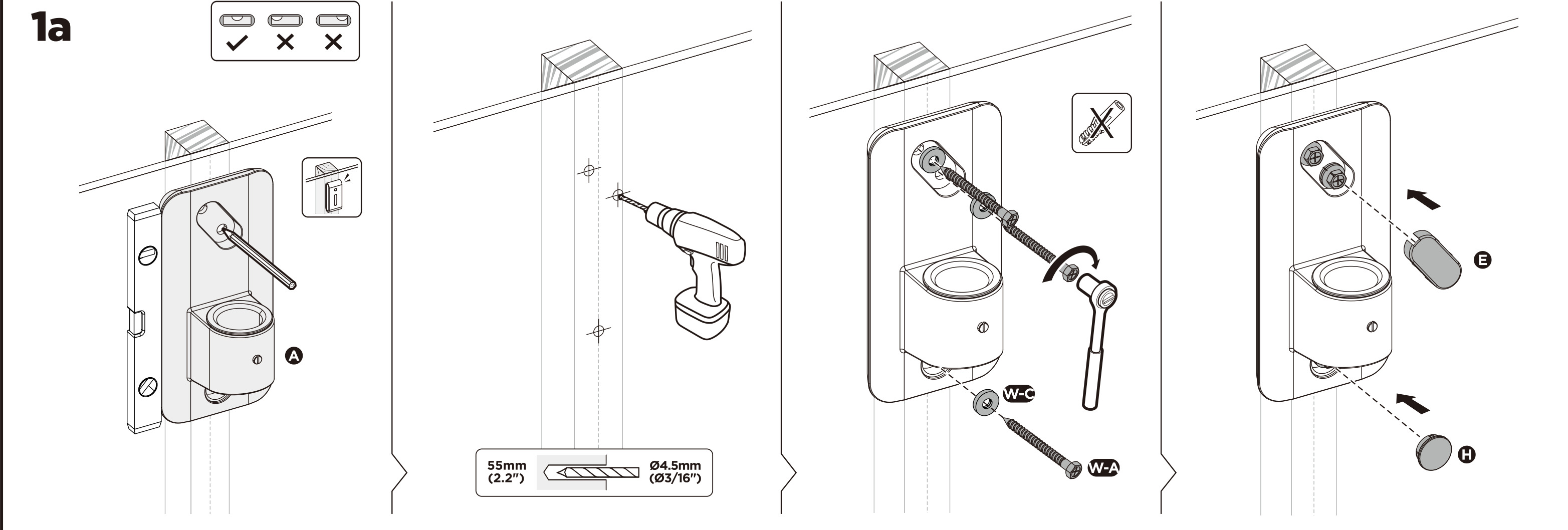
Method 1a — timber stud wall
- Find the stud with a detector and mark it. Hold the plate (A) against the wall, level it with a spirit level and mark the three holes through the plate.
- Drill the holes Ø4.5 mm to a depth of 55 mm into the stud.
- Screw the plate down with three wall screws ST6.3 × 55 mm (W-A), each with a washer D6 (W-C), and tighten them with a socket wrench.
- Press the side cover (E) and the round cover (H) into the plate to hide the screws.
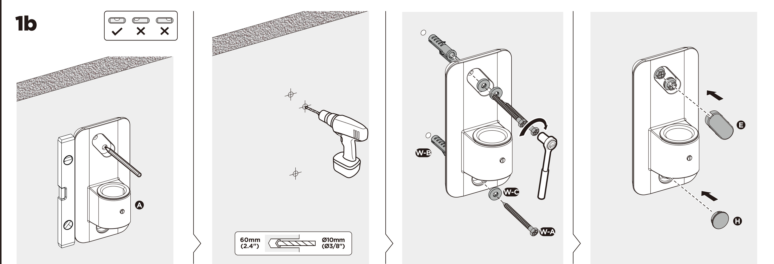
Method 1b — masonry or concrete wall
- Hold the plate (A) against the wall, level it and mark the three holes.
- Drill the holes Ø10 mm to a depth of 60 mm and tap in the three wall plugs Ø10 × 45 mm (W-B).
- Screw the plate down with three wall screws ST6.3 × 55 mm (W-A), each with a washer D6 (W-C).
- Press the covers (E) and (H) into the plate.
Do not fix the plate to plasterboard alone. It must reach a stud or solid masonry — the mount and monitor together weigh more than a plasterboard fixing can carry.
Step 2 — Fit the fixed arm
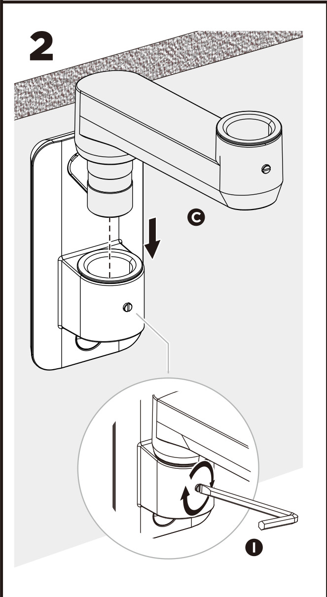
Slide the fixed arm (C) onto the post of the wall plate from above, then tighten the grub screw underneath with the 4 mm Allen key (I) so that the arm cannot be lifted off.
Step 3 — Fit the gas spring arm
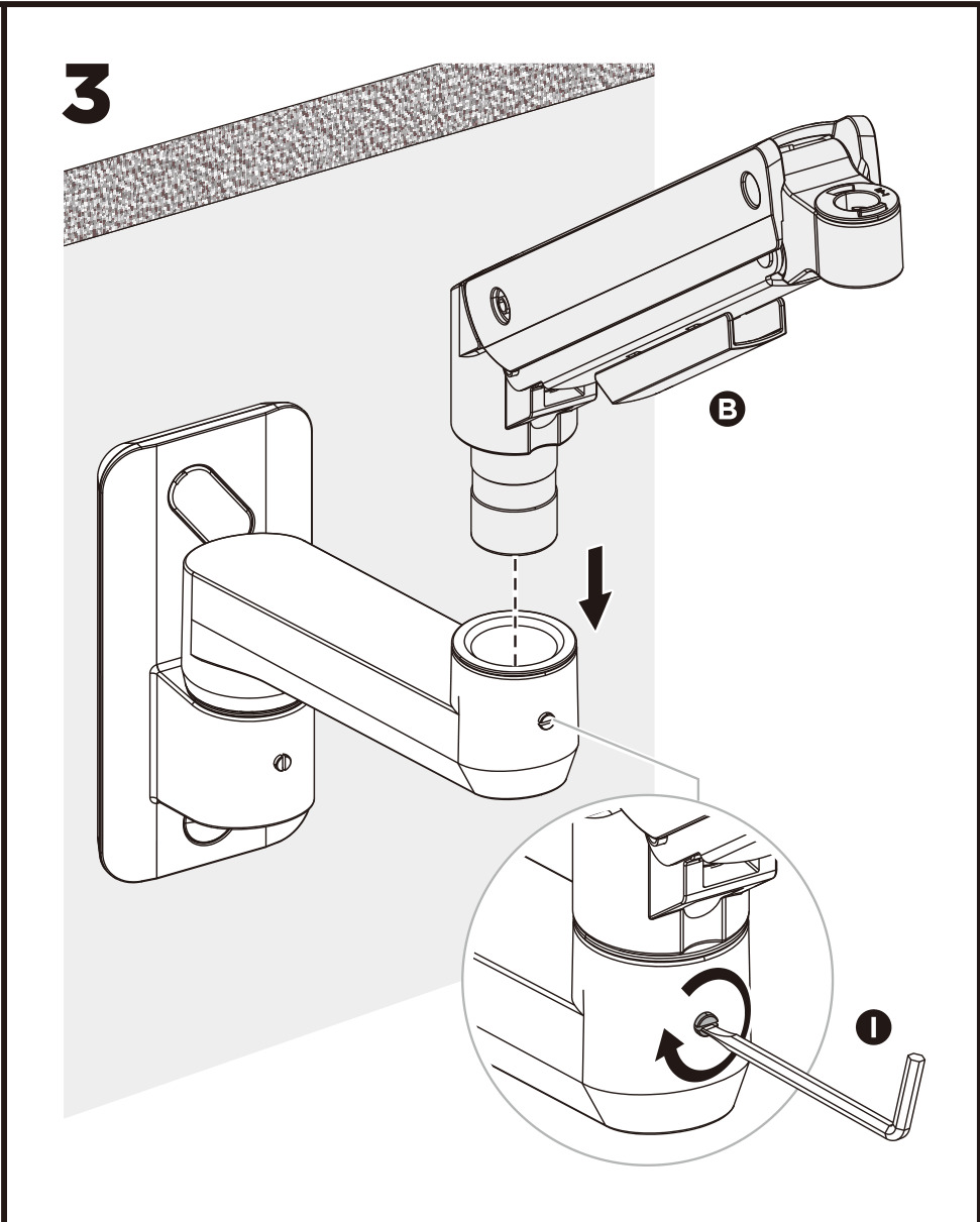
Slide the gas spring arm (B) onto the post at the end of the fixed arm (C) and tighten its grub screw with the 4 mm Allen key (I) as well.
Step 4 — Fit the VESA head
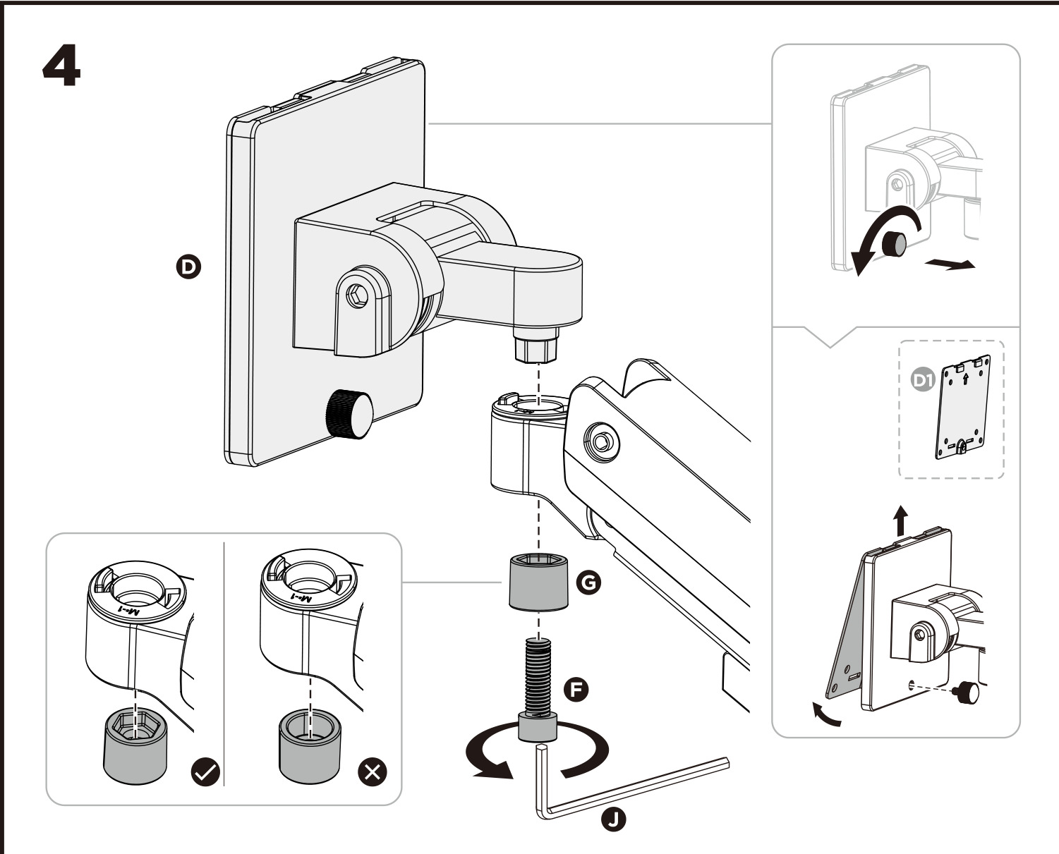
Put the spacer sleeve (G) onto the post of the head (D), drop the head onto the end of the gas spring arm and fasten it from below with the bolt M8 × 25 mm (F) using the 6 mm Allen key (J).
The sleeve must sit fully seated on the post — the drawing shows the correct and the incorrect position. The plate D1 lifts off the head; it is fitted to the monitor in the next step.
Step 5 — Fit the plate to the monitor and hang it
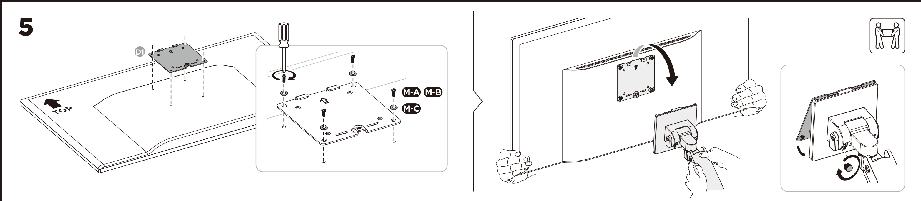
- Lay the monitor face down on a soft surface. Screw the plate (D1) to the back of the monitor with four screws — M4 × 12 mm (M-A) or M5 × 12 mm (M-B), whichever matches the threads — each with a washer D5 (M-C). The arrow on the plate points up.
- With a second person holding the monitor, hook the plate onto the head (D) from above and tighten the knob on the head so that the screen cannot slide off.
Do not let go of the monitor until the knob on the head is tightened.
Step 6 — Set the gas spring tension
The adjustment screw is at the wall end of the gas spring arm. Hold the arm horizontally with the monitor already hanging on it and turn the screw with the 6 mm Allen key (J) — this may take many turns:
- If the arm drops, turn the screw counter-clockwise until the arm holds its position.
- If the arm rises, turn the screw clockwise until it stays where you set it.
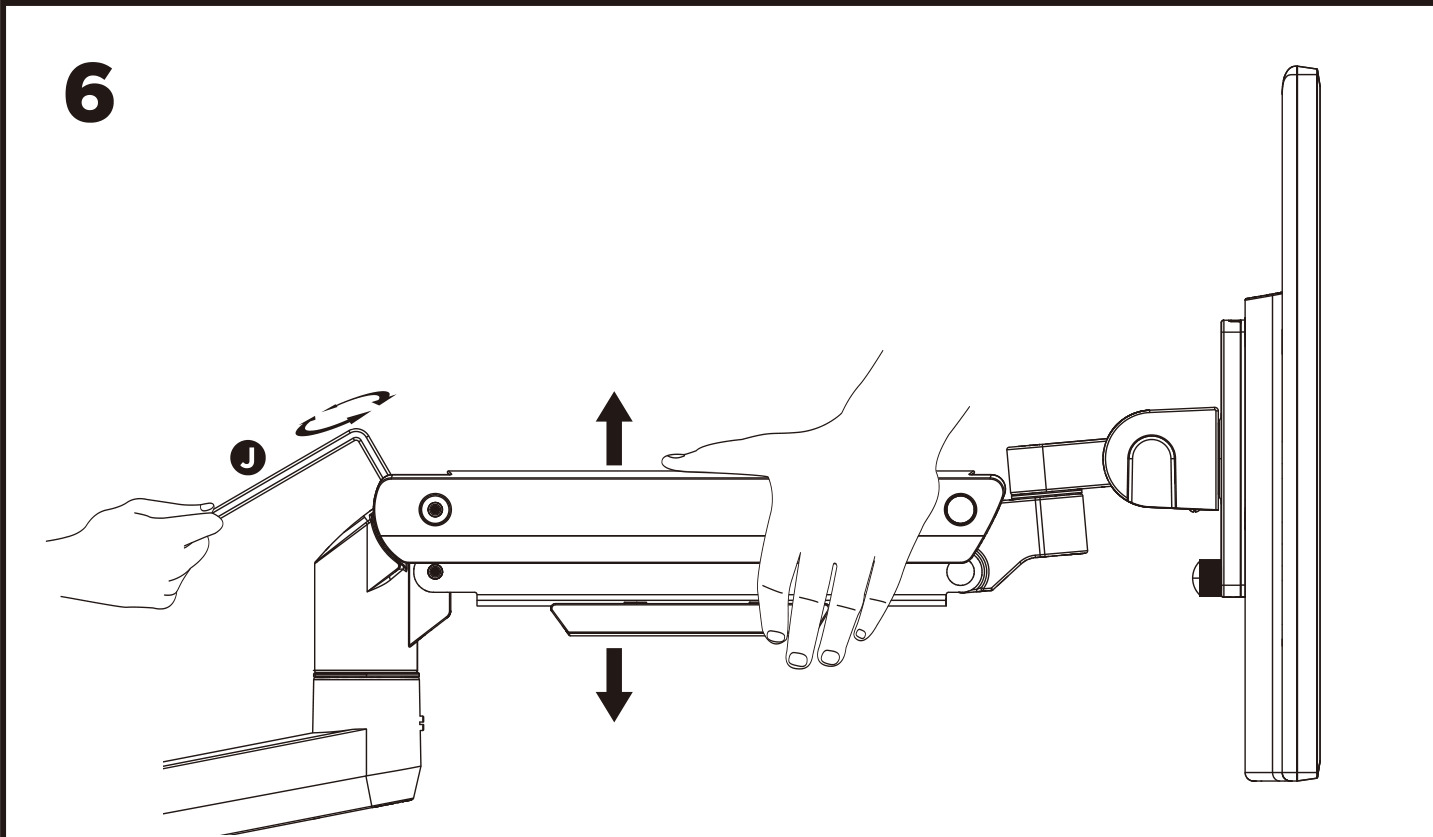
Always keep the arm horizontal while adjusting, and do not overtighten the screw. Ask for help if you cannot hold the arm and turn the key at the same time.
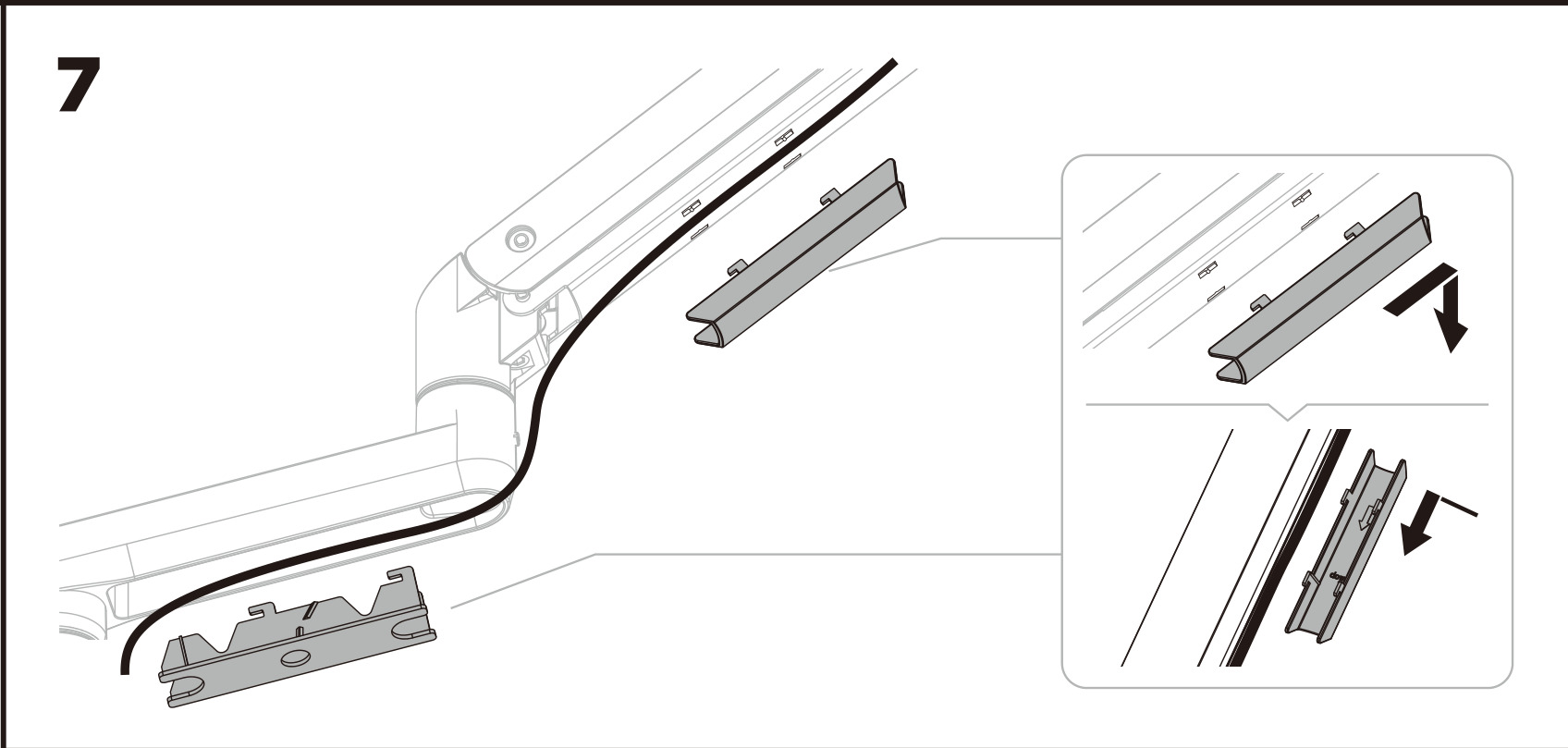
Step 7 — Run the cables
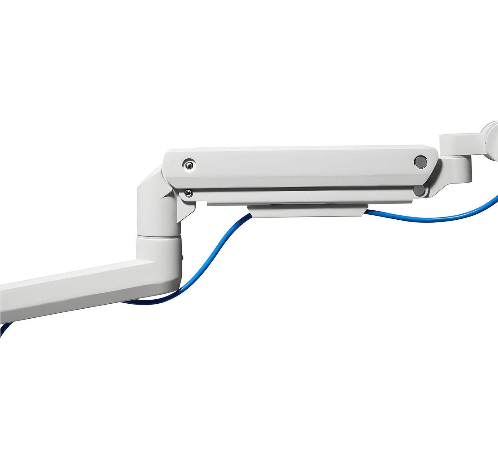
Lay the monitor cables along the arm and clip the two covers over them — one on the gas spring arm, one on the fixed arm. Leave some slack at the joints so the arm can move through its whole range.
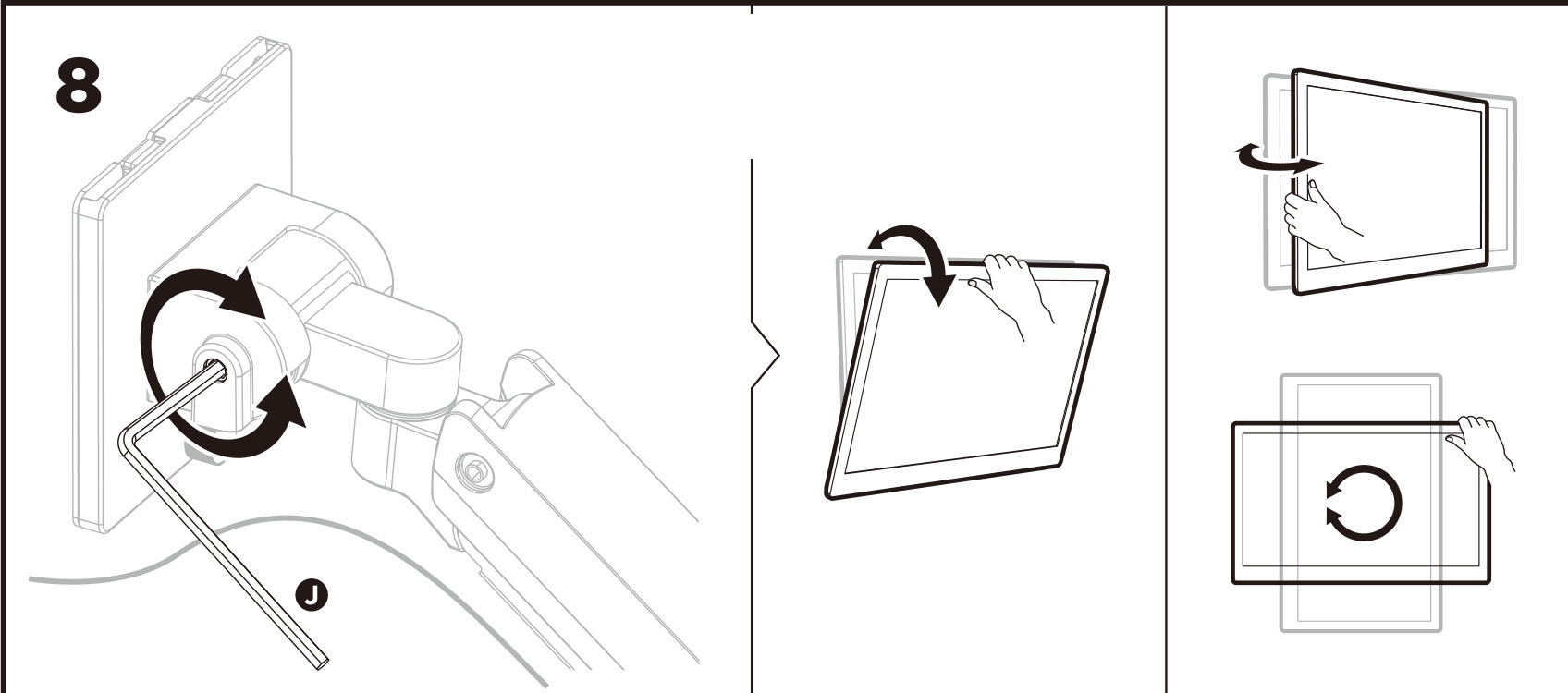
Step 8 — Set the tilt friction
Tilt and turn the screen to the position you want. If the screen does not stay where you set it, tighten the screws on the head with the 6 mm Allen key (J) as shown in the drawing.
Dimensions and ranges of movement
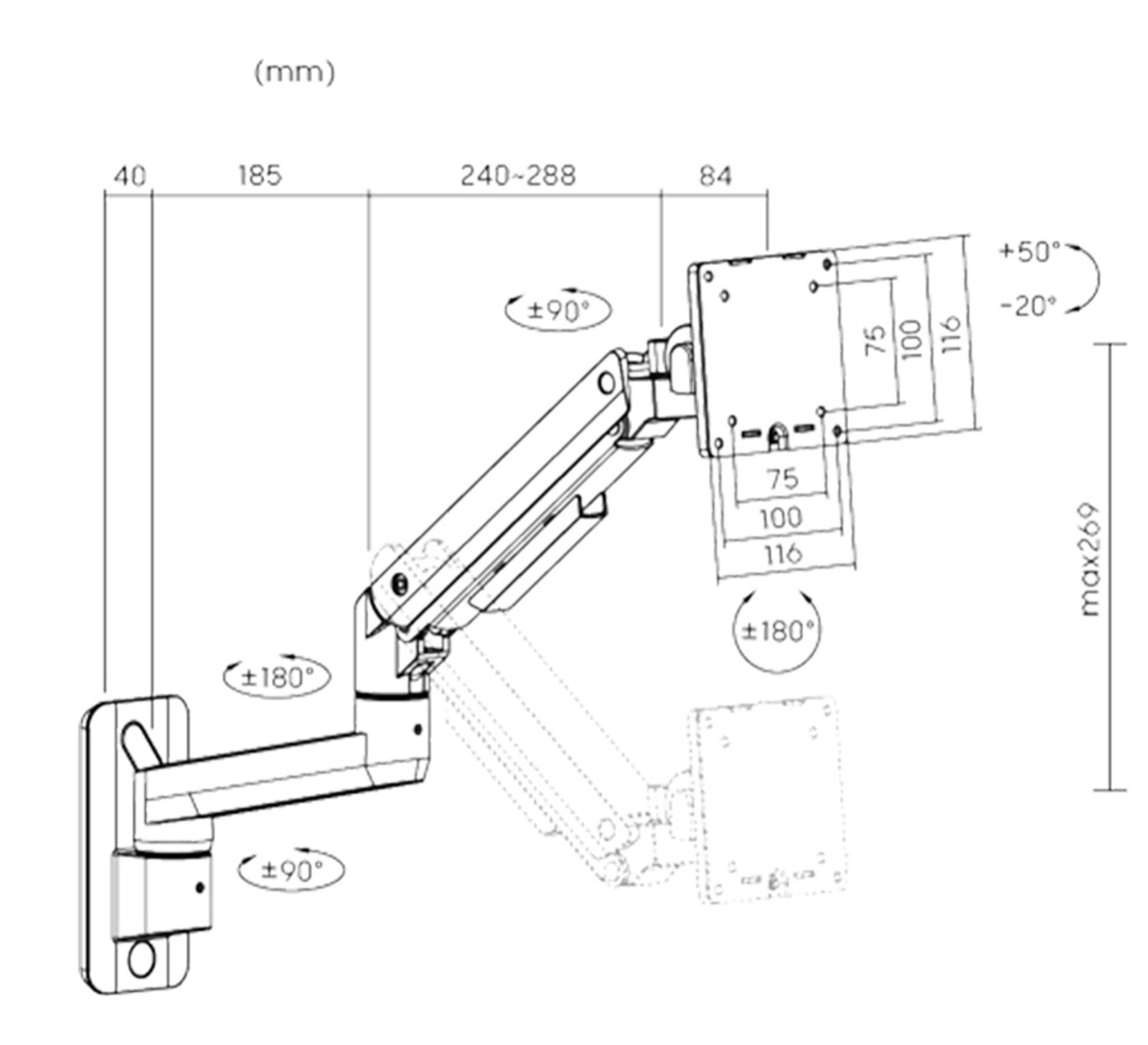
- Reach from the wall — 424 mm at full extension; the arm folds back flat when not needed
- Vertical travel — up to 269 mm on the gas spring
- Wall joint — ±90°, elbow joint — ±180°
- Monitor rotation — ±180°, so the screen can be set upright
- Tilt — from −20° to +50°
Using the mount
Once the tension is set, everything is adjusted by hand:
- Height and reach — take hold of the screen and move it; the gas spring holds it in place
- Rotation — ±90° at the wall, ±180° at the elbow, ±180° at the head
- Tilt — from −20° to +50°
- Load — one monitor of 2 to 20 kg; set the spring tension again whenever you change the monitor
- Cables — keep them under the covers, with slack at the joints
Safety rules
- Follow the installation instructions exactly. Incorrect installation may cause damage or serious injury.
- Make sure the wall safely carries the total weight of the mount, the monitor and all the fittings.
- The product should be installed by a qualified person, using the right tools and protective equipment.
- Use the supplied screws and do not overtighten them.
- The product contains small parts that pose a choking hazard if swallowed. Keep them away from children.
- The product is for indoor use only. Using it outdoors may damage it and cause injury.
Maintenance
Check at regular intervals — at least once every three months — that the mount is still firmly fixed and safe to use.
Frequently asked questions
What monitor sizes and standards are supported?
What is the load capacity?
What kind of wall can it be fixed to?
How far does the arm reach and how far does it move?
The arm drops or rises on its own — what should I do?
Can the monitor be taken off without dismantling the arm?
Downloads
Manuals and datasheets in PDF, in case an offline copy is needed. Everything they contain is also on this page.