Triple monitor arm with gas spring and USB hub, SolidHand-CM03U
GTIN: 5907614667610 · SKU: SolidHand-CM03U
The SolidHand-CM03U carries three monitors of 17 to 27 inches, up to 6 kg each, on one gas-spring arm with a crossbar. All three screens rise and fall together with a light push and reach up to 526 mm from the post; each one tilts, swivels and turns 180° to portrait on its own plate. The base holds two USB 3.0 ports and clamps to the desk edge or bolts through a hole in the desktop.
Table of contents
- Table of contents
- Specifications
- Kit contents
- Before you start
- Assembly
- Step 1 — Fix the base to the desk with the clamp
- Step 2 — Or fix the base through a hole in the desktop
- Step 3 — Fit the post and the gas-spring arm
- Step 4 — Fit the crossbar and the cable hook
- Step 5 — Fit the side rails
- Step 6 — Screw the VESA plates to the monitors
- Step 7 — Hang the monitors
- Step 8 — Balance the gas spring
- Step 9 — Close the cable covers
- Step 10 — Set the working position
- Using the arm
- Safety instructions
- Frequently asked questions
- Downloads
Specifications
- Colour: matte black
- Material: aluminium, steel, plastic
- Surface finish: powder coating
- Number of monitors: 3
- Screen size: 17–27 inches
- VESA pattern: 75 × 75 mm, 100 × 100 mm
- Weight of one monitor: 6 kg
- Height adjustment: gas spring assisted
- Arm rotation range: +10° ~ −10°
- Monitor rotation range: +180° ~ −180°
- Monitor tilt range: +5° ~ −15°
- Maximum arm reach: 526 mm
- Rotation at the base: ±90° or ±180°, set with the stop screw
- USB ports: 2 × USB 3.0 in the base
- Mounting: desk clamp (desktop 10–58 mm or 50–85 mm thick, depending on the bracket position) or grommet
- Dimensions of the mount: 133 × 70.9 × 77 cm
- Package dimensions: 63 × 32.5 × 16 cm
- Product weight: 9.5 kg
- Weight with packaging: 10 kg
Kit contents

- A — base with the USB 3.0 hub (× 1)
- B — post (× 1)
- C — gas-spring arm with head (× 1)
- D — crossbar rail, left (× 1)
- E — crossbar rail, right (× 1)
- F — centre crossbar (× 1)
- G — VESA plate (× 3)
- H — cable hook (× 1)
- I — washer plate for under the desktop (× 1)
- J — grommet plate (× 1)
- K — self-adhesive pad (× 1)
- L — clamp bracket (× 1)
- M — cable cover for the base (× 1)
- N — clamp screw with bracket (× 1)
- O — screw (× 10)
- P — screw (× 4)
- Q — screw (× 2)
- R — 3 mm Allen key (× 1)
- S — 4 mm Allen key (× 1)
- T — 6 mm Allen key (× 1)
- M-A — M4 × 12 monitor screw (× 4)
- M-B — M5 × 12 monitor screw (× 4)
- M-C — D5 washer (× 4)
The monitor screws M-A, M-B and the washers M-C are supplied in three sets — one for each monitor. Steps 1 and 2 are alternatives: use the clamp bracket (L) for the desk edge or the grommet plate (J) for a hole in the desktop.
Before you start
Assembly takes about forty minutes. Prepare the following:
- A second person — hanging the monitors on the crossbar is a two-person job
- A Phillips screwdriver; all three Allen keys (3, 4 and 6 mm) are in the kit
- A free desk edge with a desktop 10–85 mm thick, or a desktop with a hole for the grommet mount
- A check that each monitor weighs no more than 6 kg and has VESA 75 × 75 or 100 × 100 holes, and that the desk can carry the arm with three screens
Check that you have received all the parts listed above before you start. If anything is missing or damaged, contact us before assembling the arm.
Assembly
Step 1 — Fix the base to the desk with the clamp
This is the first of two mounting options. Use it when the desk has a free edge.
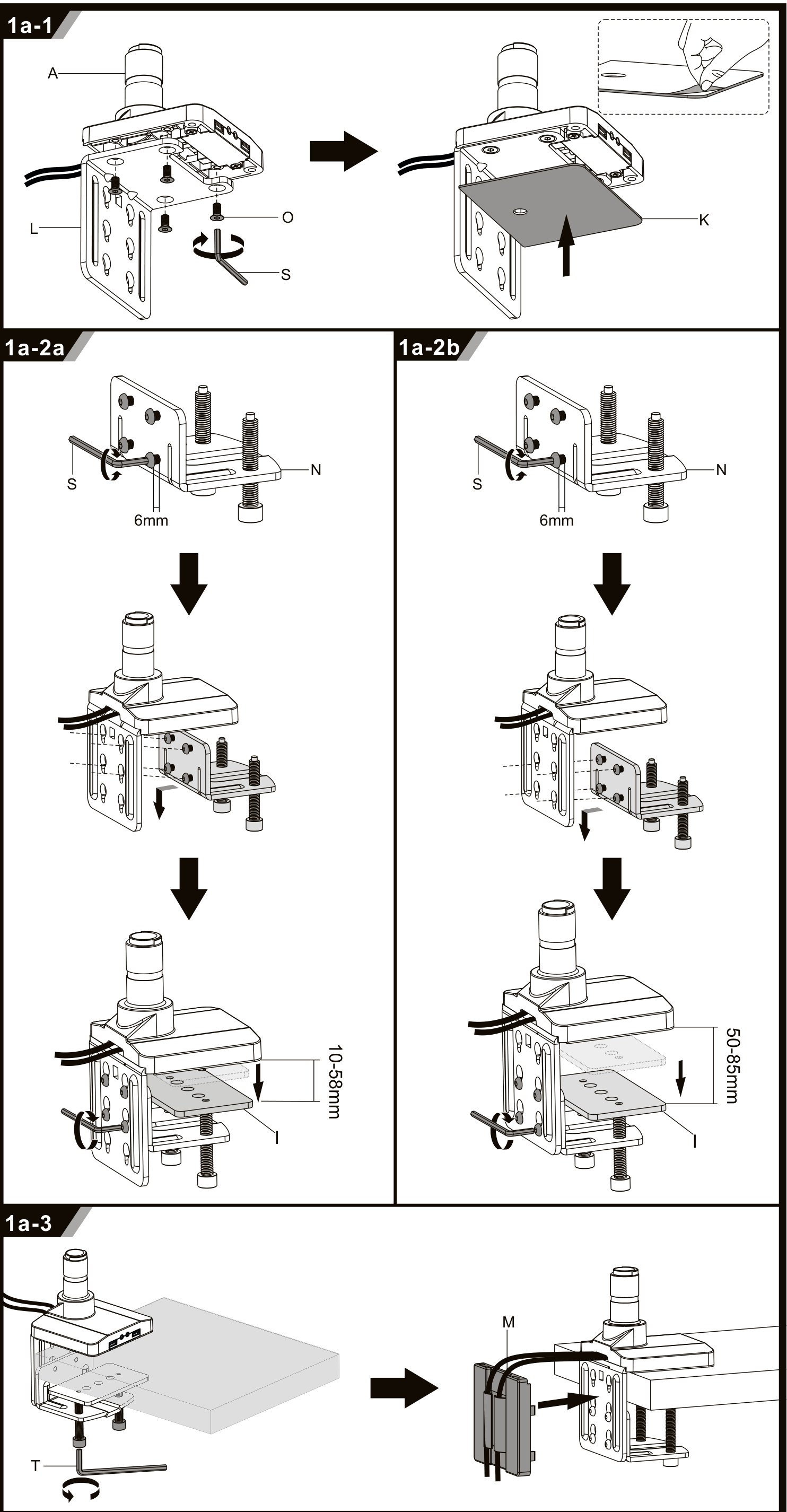
- Screw the clamp bracket (L) to the base (A) with the O screws, using the 4 mm Allen key (S), then stick the pad (K) to the underside of the base.
- Fit the clamp screw with its bracket (N) and tighten it with the 6 mm Allen key (T). The bracket has two positions: the upper one for a desktop of 10–58 mm, the lower one for 50–85 mm.
- Put the washer plate (I) between the clamp and the underside of the desktop, then tighten the clamp screw with the 6 mm Allen key (T).
- Lead the USB cables of the base down and clip the cable cover (M) onto the bracket.
Step 2 — Or fix the base through a hole in the desktop
Use this option instead of step 1 when the mount is to stand away from the desk edge. The desktop needs a hole for the bolt.
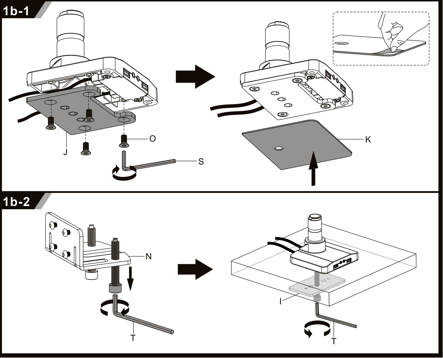
- Screw the grommet plate (J) to the base (A) with the O screws, using the 4 mm Allen key (S), and stick the pad (K) to the underside.
- Put the base on the desk with the bolt through the hole, fit the washer plate (I) from below and tighten the screw (N) with the 6 mm Allen key (T).
Step 3 — Fit the post and the gas-spring arm
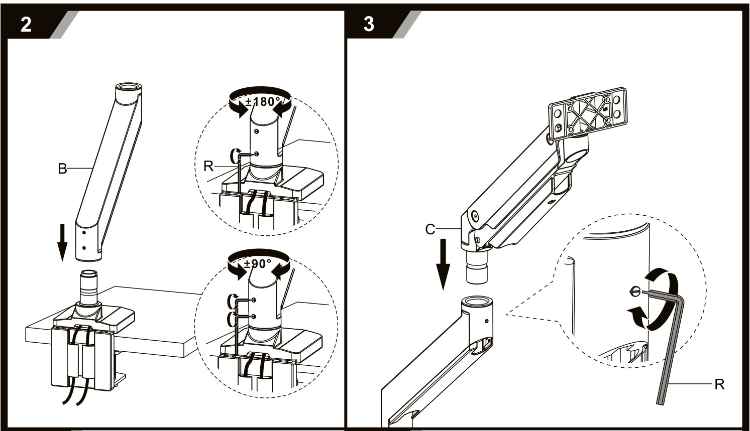
- Slide the post (B) into the base. The stop screw at its foot sets how far the arm swings: ±180° or ±90° — set it with the 3 mm Allen key (R).
- Slide the gas-spring arm (C) onto the post and lock it with the grub screw, using the 3 mm Allen key (R).
Step 4 — Fit the crossbar and the cable hook
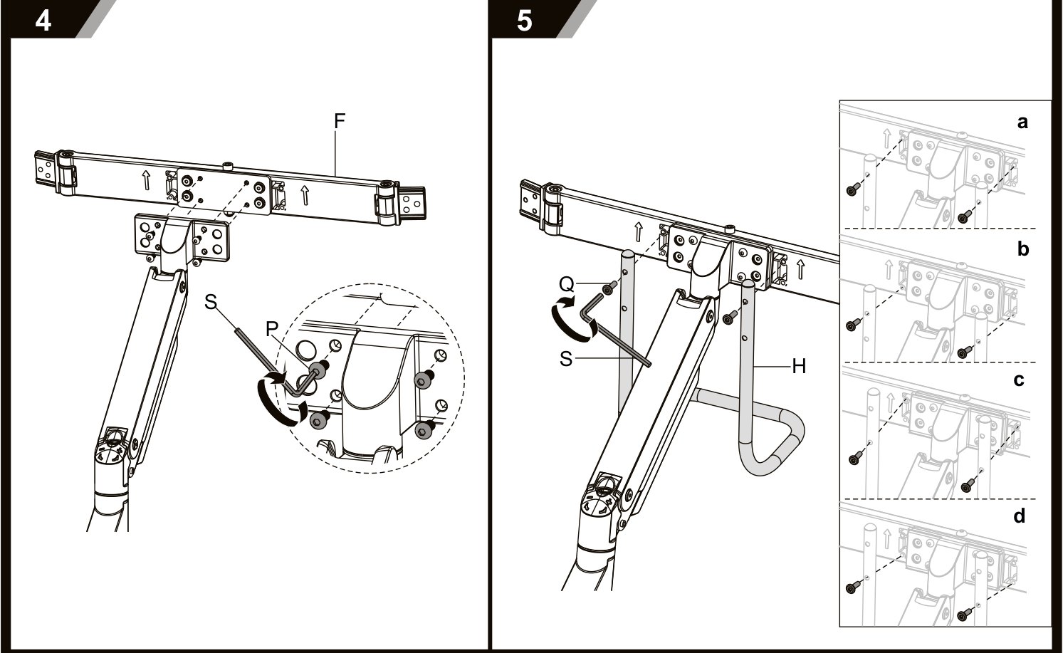
- Screw the centre crossbar (F) to the head of the arm with four P screws, using the 4 mm Allen key (S).
- Screw the cable hook (H) under the crossbar with two Q screws. The drawing shows four possible positions (a–d) — choose the one that suits your cables.
Step 5 — Fit the side rails
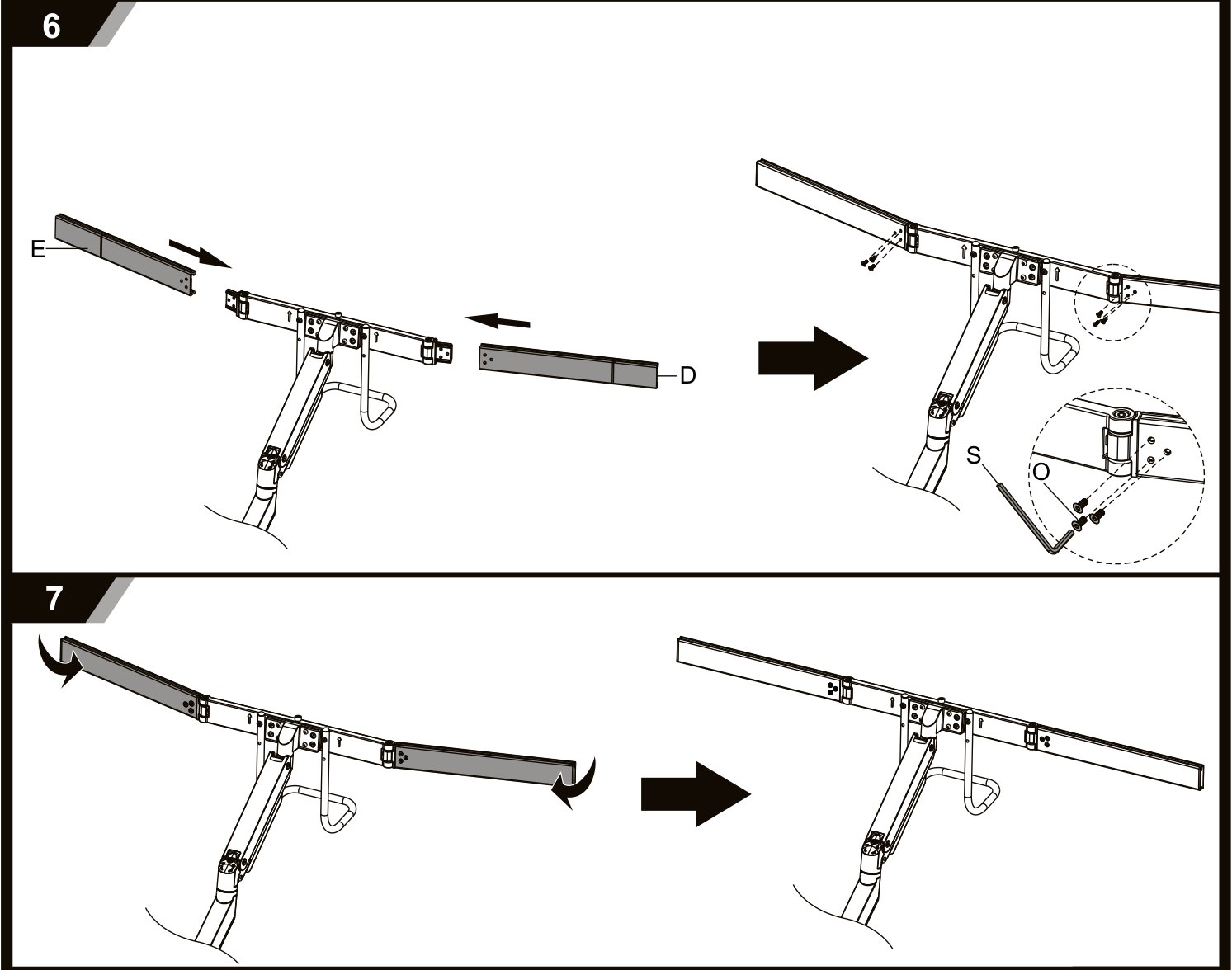
- Slide the left rail (D) and the right rail (E) into the centre crossbar and lock them with the grub screws, using the 4 mm Allen key (S).
- Set how far the rails stick out before you tighten them — that decides how far apart the side monitors sit.
- Bend the crossbar into the curve you want, as the second drawing shows, so the side screens angle towards you.
Step 6 — Screw the VESA plates to the monitors
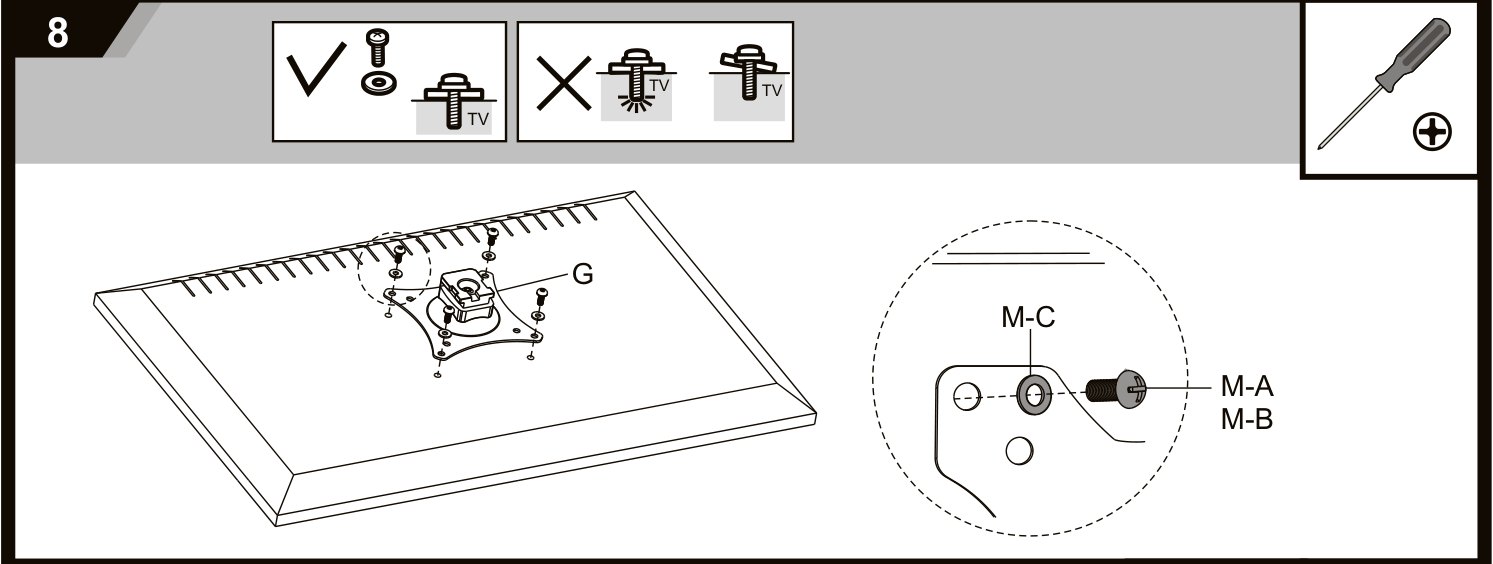
Lay each monitor face down on a soft, clean surface and fit a plate (G) to its VESA holes — 75 × 75 mm or 100 × 100 mm.
- Use the M4 × 12 (M-A) or M5 × 12 (M-B) screws with the washers (M-C), whichever thread fits the monitor.
- Pick the screw length that neither bottoms out nor is too short — the drawing shows the right and the wrong result.
- Tighten the four screws evenly with a screwdriver and do not overtighten them.
Step 7 — Hang the monitors
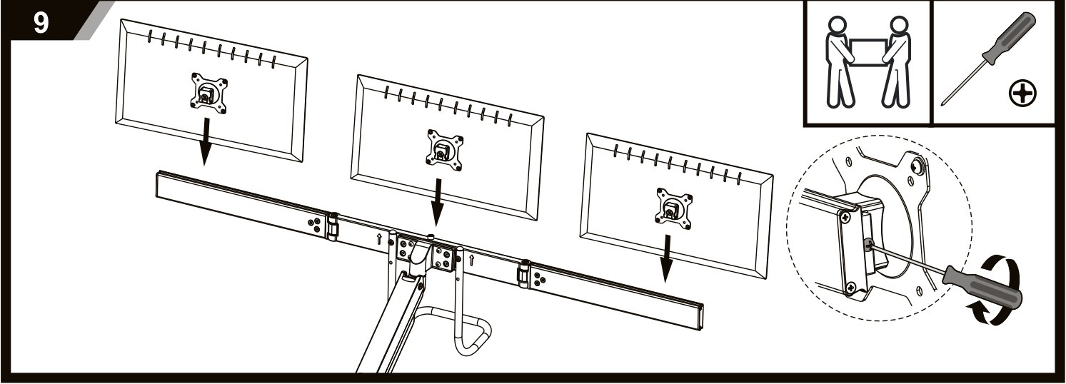
- With a second person holding the monitor, hook its VESA plate (G) onto the crossbar and let it seat.
- Secure the plate with the screw on its clip, as the inset shows.
- Repeat with the other two monitors, then slide them along the crossbar to the spacing you want.
Do not let go of a screen until its plate is hooked onto the crossbar and the screw is tightened.
Step 8 — Balance the gas spring
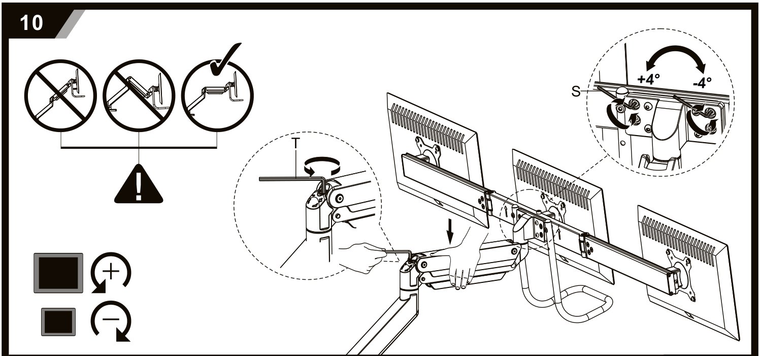
The gas spring has to match the weight of the three monitors. When it does, the crossbar stays wherever you leave it and moves with a light push. Adjust with all monitors mounted:
- Hold the arm horizontal. If it drops, turn the adjustment screw towards +; if it rises, turn it towards −, using the 6 mm Allen key (T).
- The screw at the head sets the tilt of the whole crossbar by ±4° — use it to level the three screens.
- Check the arm through its whole range and correct again if needed.
Do not load the arm beyond the rated 6 kg per monitor and do not overtighten the adjustment screw. Keep clear of the moving parts while the spring is being adjusted.
Step 9 — Close the cable covers
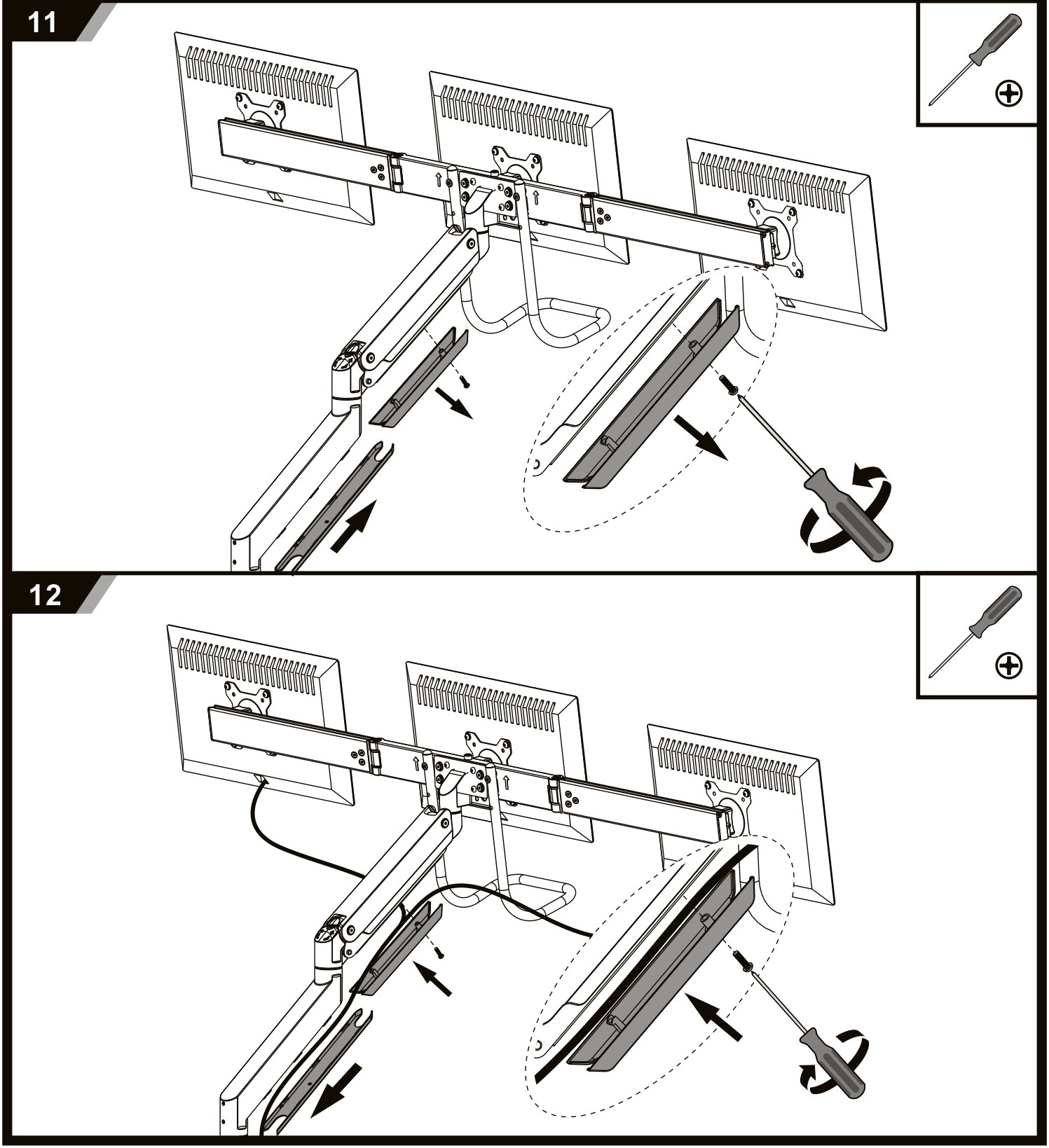
Lay the monitor cables along the arm and the crossbar, then press the covers back on with a screwdriver — first on the arm, then on the crossbar. Run the cables through the hook (H) and down to the desk.
Step 10 — Set the working position
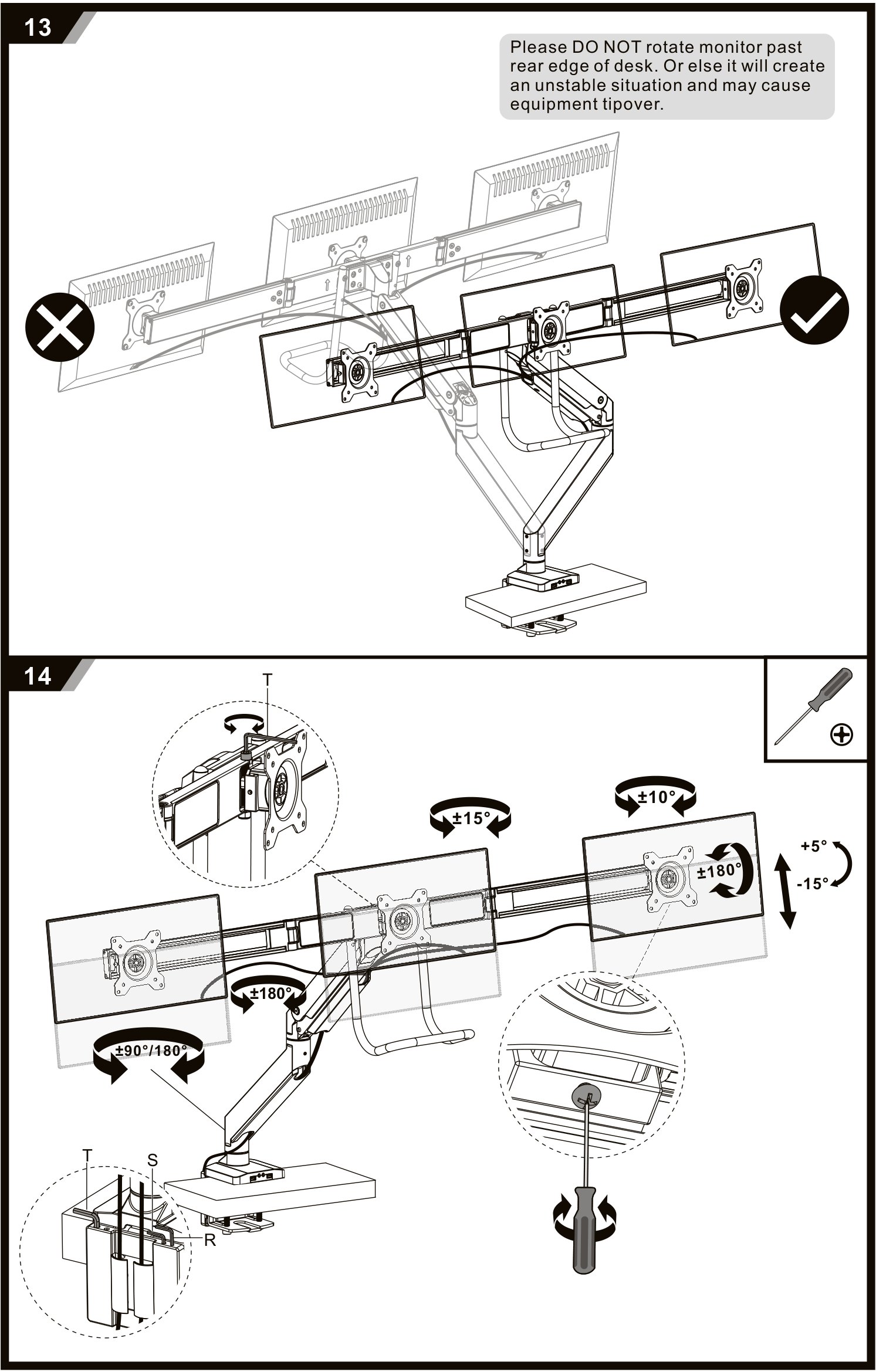
The last drawing shows every range the mount offers. Set the screens by hand and tighten the joint screws with the 6 mm Allen key (T) if a screen does not hold its angle.
- Rotation at the base — ±90° or ±180°, depending on the stop screw
- Arm rotation — ±180° at the head, ±15° and ±10° at the crossbar joints
- Screen rotation — ±180°, so any screen can be turned to portrait
- Screen tilt — +5° to −15°
Never swing the monitors out past the rear edge of the desk — the drawing marks it with a cross. The load beyond the edge can tip the whole desk over.
Using the arm
Once the monitors hang on the crossbar and the spring is balanced, every adjustment is made by hand:
- Height — all three screens rise and fall together on the gas-spring arm
- Reach — up to 526 mm from the post
- Rotation at the base — ±90° or ±180°, set with the stop screw
- Screen rotation — +180° to −180°, including portrait
- Screen tilt — +5° to −15°
- USB — two USB 3.0 ports in the base, at the front of the desk
Safety instructions
Failure to read, understand and follow all instructions can result in serious personal injury or damage to equipment.
- Make sure the mounting surface is strong enough to carry the mount together with the mounted equipment.
- Do not exceed the maximum rated load of 6 kg per monitor.
- Always work with a second person or a mechanical lift to raise and position the product safely.
- Tighten the screws firmly but never force them. Overtightening can damage the product and greatly reduce its holding power.
- Keep clear of the moving parts while using the product.
- Use the product only as intended, indoors.
- The product contains small parts that can be a choking hazard if swallowed. Keep them away from children.
Frequently asked questions
What monitor size and weight does the SolidHand-CM03U support?
How is the SolidHand-CM03U attached to the desk?
What is the USB 3.0 hub on the base used for?
Can I rotate the monitors to portrait orientation?
Why does the arm drop or rise on its own?
Downloads
The manufacturer's manuals and datasheets in PDF, in case an offline copy is needed. Everything in them is on this page as well.