Desk mount for six monitors in a 3 × 2 grid, SolidHand-CM06
GTIN: 5907614667580 · SKU: SolidHand-CM06
The SolidHand-CM06 carries six monitors of 17 to 32 inches, up to 8 kg each, in a 3 × 2 grid — three screens side by side in two rows. The weight rests on two aluminium posts fixed to the desk with clamps or through holes in the desktop. Each row is built from a centre crossbar with a side extension on the left and on the right, so every screen gets its own joint: ±180° of rotation, ±34° of tilt and ±17° of swing with its arm.
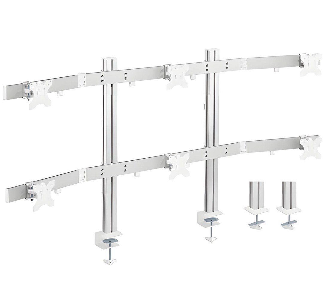
Table of contents
Specifications
- Colour: silver
- Material: aluminium, steel, plastic
- Surface finish: powder coating
- Number of monitors: 6
- Monitor diagonal: 17–32 inches
- VESA standard: 75 × 75 mm, 100 × 100 mm
- Weight of a single monitor: up to 8 kg
- Height adjustment: manual, with tools
- Arm swing range: +17° ~ −17°
- Monitor rotation range: +180° ~ −180°
- Monitor tilt range: +34° ~ −34°
- Maximum arm reach: 857 mm
- Mounting: desk clamps or grommets, two posts
- Desktop thickness: 10–50 mm with the clamps, 10–80 mm through grommet holes
- Post spacing: 470 mm with the clamps, 570 mm between grommet holes
- Mount dimensions: 178.4 × 50.3 × 57.8 cm
- Package dimensions: 103 × 42 × 12 cm
- Mount weight: 15.5 kg
- Weight with packaging: 16.5 kg
Kit contents
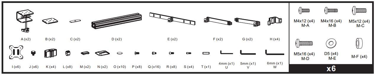
- A — desk clamp (× 2)
- B — grommet plate for under the desktop (× 2)
- C — grommet washer (× 2)
- D — aluminium post (× 2)
- E — centre crossbar (× 2)
- F — right side extension (× 2)
- G — left side extension (× 2)
- H — crossbar bracket (× 4)
- I — VESA plate (× 6)
- J — locking knob (× 6)
- K — bracket insert (× 4)
- L — cable clip (× 8)
- M — post cap (× 2)
- N — base cover (× 2)
- O — washer (× 10)
- P — base screw (× 8)
- Q — crossbar screw (× 16)
- R — extension screw (× 8)
- S — joint screw (× 4)
- T — connector sleeve (× 1)
- U — 4 mm Allen key (× 1)
- V — 5 mm Allen key (× 1)
- W — 6 mm Allen key (× 1)
Monitor screws, four of each for the six screens:
- M-A — M4 × 12 (× 4)
- M-B — M4 × 16 (× 4)
- M-C — M5 × 12 (× 4)
- M-D — M5 × 16 (× 4)
- M-E — D5 washer (× 4)
- M-F — spacer (× 4)
Before you start
Allow about two hours. This is the largest mount in the range and none of it is a one-person job.
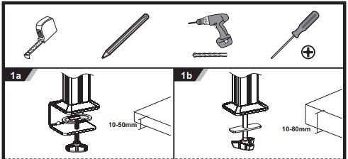
- A second person — for the crossbars and for every screen
- All three Allen keys (U, V, W) from the kit; a Phillips screwdriver for the monitor screws
- A tape measure and a pencil to set the post spacing out accurately
- For the clamps: a free desk edge with a desktop no thicker than 50 mm
- For the grommets: two Ø 12 mm holes in a desktop no thicker than 80 mm — plus a drill
- A check that each monitor weighs no more than 8 kg and has 75 × 75 or 100 × 100 VESA holes
Before you begin, check that you received every part from the list above. If anything is missing or damaged, contact us before assembling the mount. The desk carries the mount and all six screens together — around 63 kg in a full configuration — spread over two fixing points. Make sure both the desk and its top are up to it.
Assembly
Step 1 — Fix the two posts to the desk
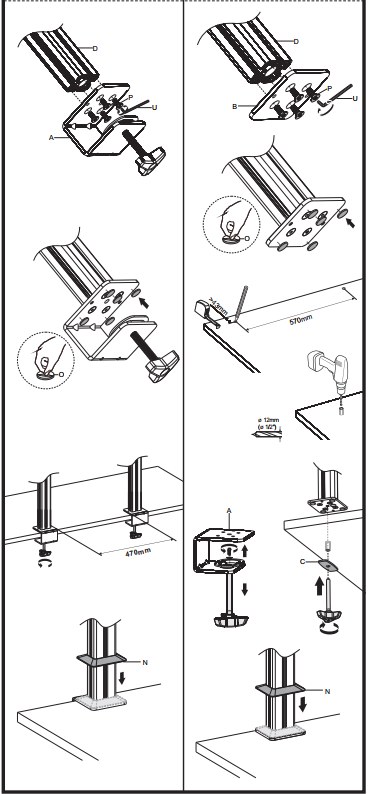
Both posts mount the same way. Choose one of the two methods before you start and set the spacing out with the tape measure first.
Option 1a — desk clamps (desktop 10–50 mm, posts 470 mm apart)
- Put a post (D) on a clamp bracket (A) and secure it from below with the base screws (P) and washers (O), using the 4 mm Allen key (U).
- Slide the assembly onto the edge of the desk and tighten the clamp screw until its foot presses firmly against the underside of the desktop.
- Repeat for the second post and set the two 470 mm apart, measured between the posts.
- Slide a base cover (N) down each post onto its base.
Option 1b — grommets (desktop 10–80 mm, holes 570 mm apart)
- Mark and drill two Ø 12 mm holes in the desktop, 570 mm apart.
- Put a post (D) on a grommet plate (B) and secure it with the base screws (P) and washers (O).
- Pass the bolt through the hole, fit the washer (C) from underneath and tighten it against the desktop.
- Repeat for the second post, then slide a base cover (N) down each post onto its base.
Step 2 — Assemble the rows and fit them to the posts
- Fit the brackets (H) with their inserts (K) to a centre crossbar (E), one at each post position, and set them with the 4 mm Allen key (U).
- Slide the assembled row down over both posts from above.
- Set its height and lock it. Repeat with the second row.
- Leave more room above the upper row than between the two rows — the top screens need the space to tilt freely.
Set the lower row so the bottom screens sit just above the desktop and the upper row lands near eye level. The height only changes with an Allen key and each row needs two people to move, so it pays to get it right the first time.
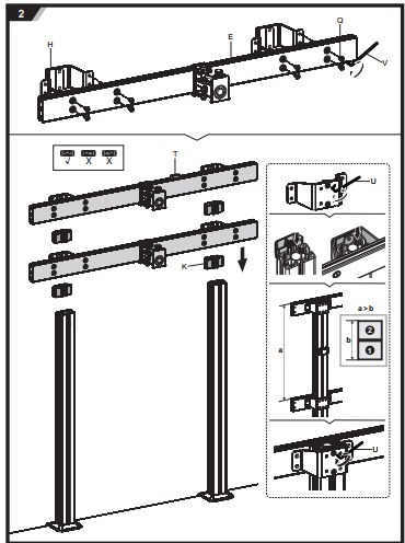
Step 3 — Attach the side extensions
- Slide the left extension (G) into the left end of a centre crossbar (E) and the right extension (F) into the right end.
- Fasten each one with the extension screws (R) using the 4 mm Allen key (U); secure the joints with the joint screws (S) where the drawing shows them.
- Repeat on the second row, then press the caps (M) onto the tops of both posts.
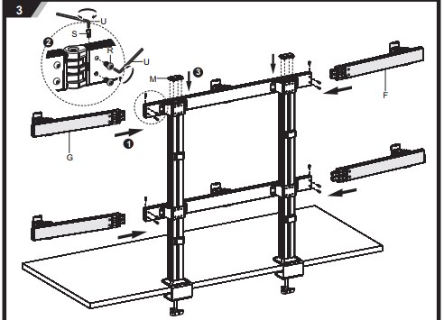
Step 4 — Attach the VESA plates to the monitors
Lay each monitor face down on a soft, clean surface and match a plate (I) to its VESA holes — 75 × 75 mm or 100 × 100 mm.
Monitor with a flat back
- Fasten the plate directly to the monitor with four M4 × 12 (M-A) or M5 × 12 (M-C) screws and the washers (M-E), whichever thread fits.
Monitor with a curved back or recessed holes
- Put one spacer (M-F) between the plate and the monitor at each of the four holes.
- Fasten the plate with four M4 × 16 (M-B) or M5 × 16 (M-D) screws and the washers (M-E) — they are long enough to reach through the spacers.
Tighten the four screws evenly and do not overtighten them — the thread is in the monitor housing. Repeat for all six monitors.
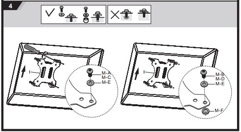
Step 5 — Hang the monitors
- With the second person holding the monitor, slide the pin of its VESA plate (I) into a joint on the crossbar.
- Screw the locking knob (J) onto the pin from above and tighten it firmly by hand.
- Do not let go of the screen until its knob is tight. Work along the lower row first, then the upper one.
Never release a screen before its knob (J) is tight — an unsecured monitor can slide off the joint. With six screens the mount also gets top-heavy as you go, so fill the lower row first.
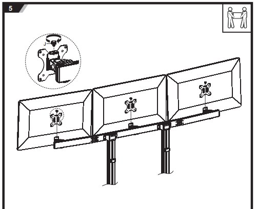
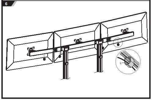
Step 6 — Route the cables
- Clip the cable clips (L) onto the crossbars — four per row.
- Lay the monitor power and signal cables in the clips, then run them down along the posts to the desk.
Step 7 — Adjust the screens
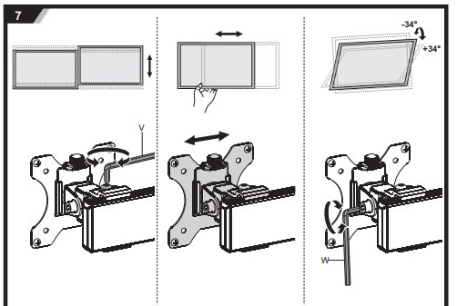
- Slide each screen along its crossbar to set the spacing, and loosen or tighten the joint with the 5 mm Allen key (V) to set how firmly it holds.
- Set the tilt resistance with the 6 mm Allen key (W): tighten if a screen drops under its own weight, loosen if it is hard to move.
- Aim for a setting where each screen holds its position but can still be moved with one hand.
Step 8 — Check the movement ranges
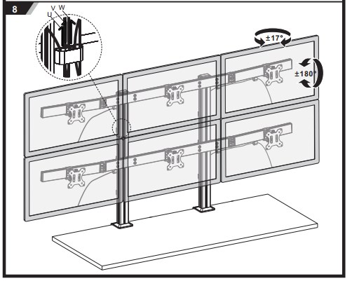
With all six screens mounted and the joints set, check that each one moves freely and clears its neighbours through the whole range: ±17° of arm swing and ±180° of rotation. With screens this close together, check the corners of the upper row against the lower one as you tilt.
Using the mount
Once the screens hang on the crossbars and the joints are set, you position them by hand:
- Reach — up to 857 mm from the posts at the widest setting
- Arm swing — ±17° on each joint, independently for every screen
- Screen rotation — ±180°, so any screen can be turned to portrait
- Screen tilt — ±34°
- Height — set on the posts with the 4 mm Allen key (U); all three screens in a row move together
Safety instructions
Failure to read, understand and follow all the instructions may result in serious injury or damage to equipment.
- Using the mount with a monitor heavier than the permitted 8 kg causes instability and may lead to injury or damage to the screen.
- Follow the assembly instructions closely. Incorrect installation may cause damage or serious injury.
- Use proper protective equipment and the right tools. The product should be installed by professionals.
- Make sure the desk safely carries the combined weight of the mount and all six monitors, and that the desktop is no thicker than 50 mm at the clamps or 80 mm at the grommets.
- Use the supplied screws and do not overtighten them.
- The product contains small parts that pose a choking hazard if swallowed. Keep them away from children.
- The product is intended for indoor use only. Outdoor use may damage it.
- Check that the clamps and the screws are still tight at least once every three months.
Frequently asked questions
Which monitors fit the SolidHand-CM06?
How much does the desk have to carry?
How far apart do the posts go?
Do I have to drill holes in my desk?
Can I mount fewer than six monitors?
Can I turn a monitor to portrait?
Downloads
Manufacturer manuals and datasheets in PDF, in case an offline copy is needed. Everything in them is also on this page.