Working time recorder with fingerprint and RFID, CTR10
GTIN: 5906935203637 · SKU: CTR10
The CTR10 is a standalone working time recorder. Everything it needs is inside the housing: employees are enrolled on the device, clock in on the device, and reports are written straight to a USB flash drive. No computer, no software installation and no cloud account are involved. The same unit can also open an electric door lock, so a single device covers both attendance and access to one room.
Table of contents
- Table of contents
- Specifications
- Kit contents
- Panel
- Ports
- Access-control connector
- Mounting
- Setting the recorder up for the first time
- Menu structure
- Shifts
- Departments
- Attendance rules
- Employees
- Clocking in and out
- Checking records on the device
- Downloading reports to a USB drive
- Summing hours with ClockSum
- Access control, door lock, bell and Wiegand
- Troubleshooting
- Downloads
Specifications
- Material: ABS + PC
- Identification methods: fingerprint, PIN, RFID card or key fob
- RFID frequency: 125 kHz
- Maximum number of employees: 1000
- Maximum number of administrators: 10
- Maximum number of fingerprints: 1000
- Maximum number of PINs: 1000
- Log capacity: 100 000 entries
- False acceptance rate: 1/1 000 000
- Display: 2.4" TFT LCD
- Keypad: 17 keys
- Menu language: English
- Report export: USB flash drive formatted as FAT32
- Ports: USB-A, 12-pin access-control connector
- Access control: relay output for an electric lock
- Bell: built-in sounder or relay output
- Wiegand input and output: WG26 / WG34
- Power supply: 12 V DC
- Ingress protection: IP54
- Operating temperature: 0 to 60 °C
- Operating humidity: 20–80%
- Device dimensions: 10.6 × 10.6 × 3.4 cm
- Package dimensions: 14.5 × 14 × 4.5 cm
- Device weight: 155 g
- Weight with packaging: 200 g
Kit contents
- CTR10 working time recorder
- Access-control wiring harness, 20 cm, with a 12 V power supply
- Wall plugs and mounting screws
- Manufacturer's printed manual
- Electronic user manual
The recorder does not have to run from the supplied adapter. The same 12 V pair on the harness can be fed from a building's low-voltage installation — the kind that already powers door phones or alarm panels.
Panel
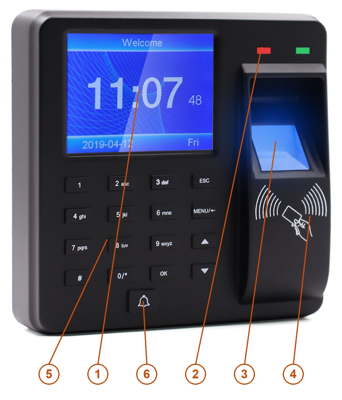
- Display — 2.4" colour TFT LCD showing the clock, the verification result and the menu.
- Status LEDs — the green one confirms a successful reading, the red one signals a rejected one.
- Fingerprint sensor — optical, reads the finger placed on it.
- RFID field — hold the 125 kHz card or key fob against the symbol.
- Keypad — 16 keys for entering IDs, PINs and text.
- Bell key — triggers the bell signal.
What each key does
| Key | Function |
|---|---|
| 0–9 | Enter digits; also letters when a name is being typed |
| ESC | Cancel or leave the current setting; also deletes characters in a text field |
| MENU/← | Open the main menu; inside the menu it works as the backspace and as the delete key for a stored fingerprint |
| ▲ / ▼ | Move the cursor between items and fields |
| OK | Confirm the selection or the entered value |
| # | Switch the input mode between digits and letters |
| Bell | Sound the bell |
Entering names
Names are typed on the numeric keys the way they used to be on a mobile phone: each key carries three or four letters, printed next to the digit, and pressing the key repeatedly steps through them. # switches between digits and letters, and ESC deletes the last character. The device knows the 26 letters of the English alphabet — accented characters cannot be entered, so type employee names without diacritics.
Ports
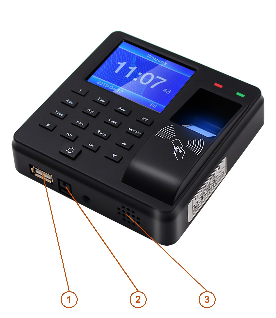
- USB-A — a flash drive for exporting reports and for importing the employee form.
- Power socket — 12 V DC from the supplied adapter.
- Speaker — voice prompts and the bell signal.
The access-control lines — the door lock, the exit button, the bell and both Wiegand directions — are on a separate 12-pin connector on the back of the recorder, reached with the supplied harness. See Access control, door lock, bell and Wiegand.
Access-control connector
The 12-pin socket sits in the recess on the back of the housing, behind the wall bracket. The supplied harness plugs into it and brings all the signals out as loose wires.
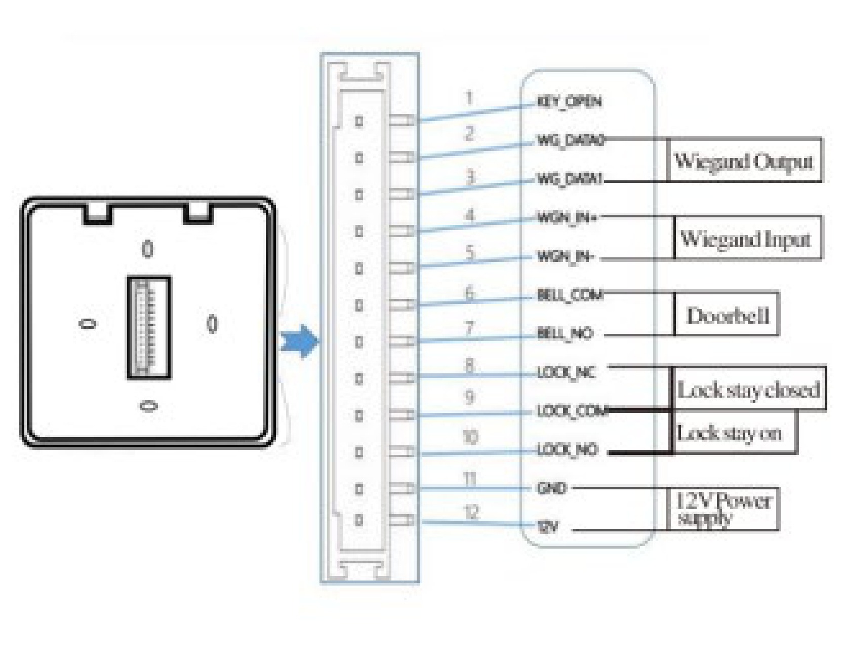
| Pin | Signal | Meaning |
|---|---|---|
| 1 | KEY_OPEN | Exit button input — shorting it to ground releases the lock without a clocking |
| 2 | WG_DATA0 | Wiegand output, DATA0 |
| 3 | WG_DATA1 | Wiegand output, DATA1 |
| 4 | WGN_IN+ | Wiegand input, DATA0 — from an external reader |
| 5 | WGN_IN− | Wiegand input, DATA1 — from an external reader |
| 6 | BELL_COM | Bell relay, common contact |
| 7 | BELL_NO | Bell relay, normally open contact |
| 8 | LOCK_NC | Lock relay, normally closed contact — for a lock that stays closed |
| 9 | LOCK_COM | Lock relay, common contact |
| 10 | LOCK_NO | Lock relay, normally open contact — for a lock that stays powered |
| 11 | GND | Ground of the 12 V supply |
| 12 | 12 V | 12 V DC supply |
Pins 4 and 5 are both labelled WGN_IN+ on the manufacturer's diagram. That is a printing error in the original drawing — pin 4 is the plus line and pin 5 the minus line of the Wiegand input.
Mounting
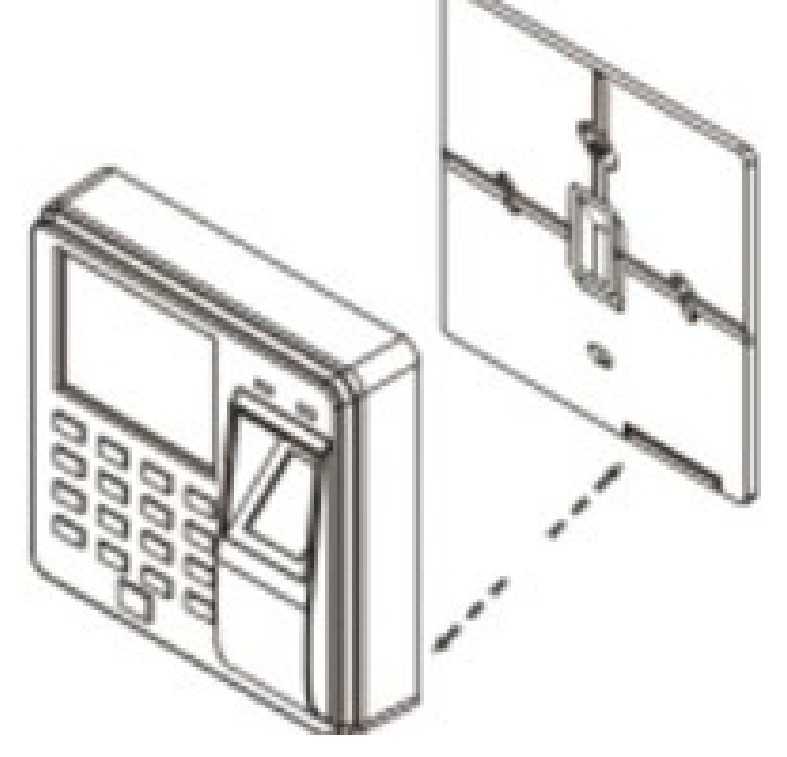
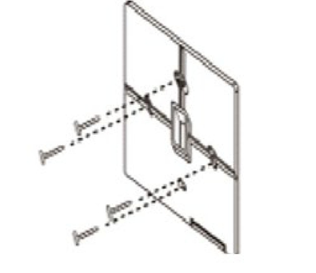
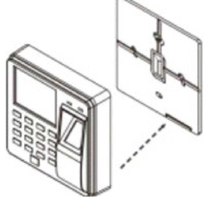
The recorder hangs on a back cover that is screwed to the wall. Mount it at about eye level, in a spot where no strong light falls on the fingerprint sensor — the sensor is optical, and direct sunlight or a lamp shining into it noticeably lowers recognition.
-
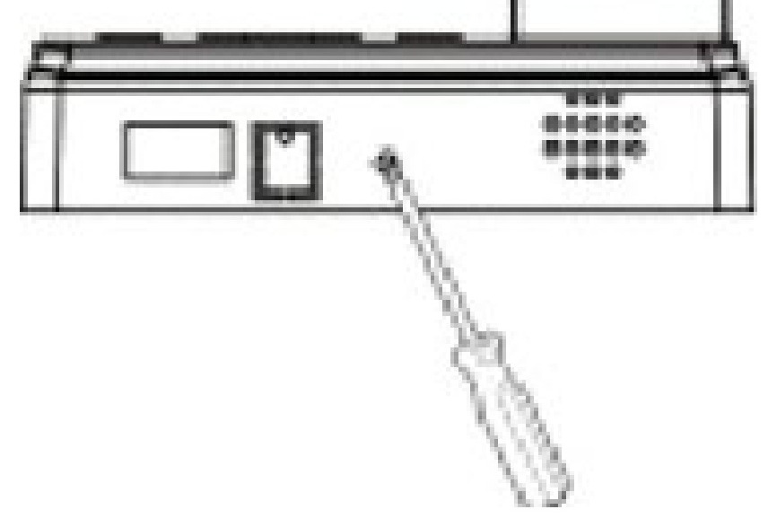
Undo the screw on the bottom edge with a screwdriver.
-
Lift the recorder off its back cover.
-
Drill the holes, put in the wall plugs and screw the back cover to the wall.
-
Feed the harness through the opening in the cover and hang the recorder on it.
-
Lock the recorder to the cover with the bottom screw.
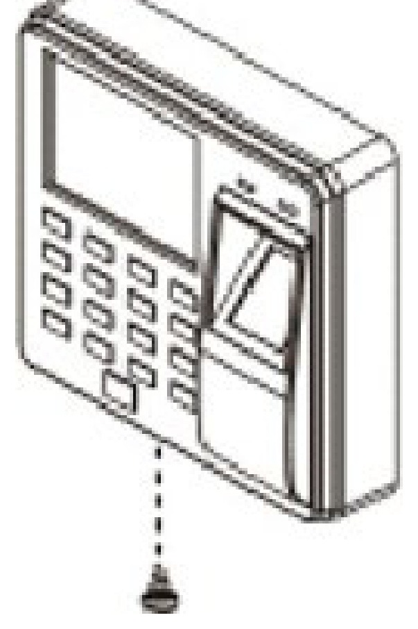
The back cover carries a tamper switch. Once the recorder is screwed on, taking it off the wall is detected by the device.
Setting the recorder up for the first time
Work through it in this order — each step relies on the one before it:
- Shifts — define the working hours the company keeps.
- Departments — name the departments and assign a shift to each day of the week.
- Employees — enrol people and give each one a fingerprint, a card or a PIN.
- Clocking — employees start clocking in and out.
- Reports — export them to a USB flash drive.
If your company works standard hours and one department is enough, only the employees have to be enrolled: the recorder starts with Shift 1 already in place and applies it by default.
Menu structure
Press MENU on the home screen to open the main menu:
| Item | What it holds |
|---|---|
| Employee | Enrolling, editing and deleting employees |
| Attendance | Downloading reports and the employee form to a USB drive, uploading it back |
| Attend. Rules | Company name, shifts, departments, scheduling and attendance tolerances |
| Log Query | Browsing clockings on the display, by employee ID or by date |
| Setting | Device settings — date and time, sound, and the administrator password |
| About | Device information: model, firmware and the number of records held |
ESC always steps back one level, OK goes one level deeper.
Shifts
A shift is a set of working hours: a morning period, an afternoon period and an overtime window. Up to 10 shifts can be defined.
- Press MENU, select Attend. Rules and press OK.
- Select Shift and pick the shift to edit, for example Shift 1.
- Move between the fields with ▲ and ▼. The left-hand pair of columns is the hour and minute the period starts, the right-hand pair is the hour and minute it ends.
- Press OK to save, ESC to leave.
Each shift has three lines:
| Line | Meaning |
|---|---|
| Time 1 | The first period of the day, typically the morning |
| Time 2 | The second period, typically the afternoon after a break |
| Overtime | The overtime window |
Example — one shift, no overtime. The company works from 08:00 to 17:00 and employees clock in twice a day:
Time 1     08:00 – 17:00
Time 2     00:00 – 00:00
Overtime   00:00 – 00:00
A period left at 00:00 – 00:00 is not used.
Departments
The recorder holds a list of departments. A department carries both a name and a weekly schedule, so people who work different hours are separated by putting them in different departments.
Naming a department
- Press MENU, select Attend. Rules, press OK.
- Select Department and press OK.
- Pick the department from the list and press OK.
- Type the new name on the numeric keys and press OK to save.
The weekly schedule
Inside a department, open its schedule to set which shift applies on which day of the week. Every day carries a number:
- 1–10 — the employees of that department work shift 1 to 10 that day
- 0 or an empty field — a day off
When the rota is complicated, or when the whole department cannot be served by a single weekly pattern, download the employee form to a USB drive instead (Attendance → Download Employee Form), set the shifts and the schedule per employee in the spreadsheet, and upload the form back to the recorder.
Attendance rules
MENU → Attend. Rules also holds the settings that apply to the whole device:
- Company — the company name shown on reports
- Shift — the working hours, as above
- Department — the departments and their weekly schedules
- Scheduling — whether the schedule is taken from the department or per employee
- Attend. Time Allowed — the tolerances: how late a clocking may be before it counts as late, how early an employee may leave, and how long the device waits before it accepts the same person again
If the default rules suit your company, nothing here has to be changed.
Employees
Adding an employee
- Press MENU, select Employee and press OK.
- Select Enroll and press OK.
- Fill in the fields:
- ID — the employee number. The recorder proposes the next free one; up to 1000 employees can be held.
- Name — typed on the numeric keys.
- Dept. — press OK and pick the department from the list.
- Move down to the Enroll button, press OK to save and ESC to leave.
Fingerprint, card and PIN
Identification is added after the employee exists. Go to MENU → Employee → Browse, pick the person with ▲ / ▼ and OK, and fill in the entries of the employee record:
| Entry | What it does |
|---|---|
| ID | The employee number given at enrolment |
| Name | The employee name, editable |
| Finger | Registers a fingerprint. Press the same finger on the sensor as many times as the counter on the screen asks — the device confirms when the print is complete. Press MENU inside this entry to delete a stored fingerprint. |
| Card | Assigns an RFID card or key fob — hold it against the RFID field |
| Password | A PIN of up to 6 digits |
| Dept. | The department the employee belongs to |
| Authority | The privilege level — a normal user or an administrator |
An employee can hold all three identification methods at once and use whichever is convenient: a finger with wet or damaged skin can still clock in with the card or the PIN.
Give administrator rights sparingly, and note the administrator password down. Once an administrator exists, the menu is closed to everyone else — and the device has no factory bypass. If the password is lost, contact HDWR support with the serial number and proof of purchase.
Editing and deleting
The same MENU → Employee → Browse list is used to change an employee's data or to remove the person from the device. Removing an employee does not remove the clockings already recorded — those stay in the log until the log is cleared.
Clocking in and out
On the home screen an employee identifies themself in one of three ways:
- Fingerprint — place the finger on the sensor.
- Card or key fob — hold it against the RFID field.
- PIN — type the employee ID, press OK, type the PIN and press OK.
The recorder confirms with a voice prompt and the green LED, and writes the clocking to its log with the date and time. A rejected reading is signalled by the red LED — repeat it or use another method.
The device holds 100 000 clockings. When the log fills up, the oldest entries are overwritten, so export reports regularly.
Checking records on the device
Individual clockings can be read straight from the display without a computer, through MENU → Log Query:
- By employee ID —
MENU → Log Query → ID → Browse → enter the ID → OK - By date —
MENU → Log Query → Date → Browse → enter the date → OK
Downloading reports to a USB drive
-
Plug the flash drive into the USB-A socket on the bottom edge.
-
Press MENU, select Attendance and press OK.
-
Pick what to write to the drive:
Option What it writes Download All Report The clockings of all employees Download Individual Report The clockings of one employee Download Employee Form The employee list as a spreadsheet, for editing on a computer Upload Employee Form Reads the edited form back into the recorder Download Employee Data The employee database, including fingerprints, as a backup -
Enter the period the report is to cover and press OK.
-
The recorder writes an Excel file to the drive. Open it on any computer.
The drive must be formatted as FAT32. A drive in another file system is not recognised — format it as FAT32 and plug it in again.
Summing hours with ClockSum
The recorder counts the hours it was told about — the periods defined in the shift. Time worked outside them is recorded as clockings, but the device does not add it up. For this, use ClockSum — a paid program specially developed by the HDWR team. It loads the Excel report exported from the CTR10 and turns it, within moments, into a clear summary of hours for each employee, ready to hand over to HR or payroll.
How to create the summary
- Export the report from the recorder to a USB flash drive and copy it to the computer.
- Start ClockSum and drag the report file (.xlsx / .xls) into the program window — exactly as the recorder saved it, without tidying it up first. The program recognises the clocking log by its layout, so the sheet name and the language set on the recorder do not matter.
- Choose how breaks are counted: do not add breaks, add a standard break of up to 20 minutes a day, or add all breaks. The selected setting is saved in the output file next to the calculated hours.
- Save the summary. ClockSum creates a new .xlsx file, and the original report from the recorder is left unchanged.
How ClockSum handles difficult cases
- Night shift. Clockings are paired on one continuous timeline, so a shift from 22:00 to 6:00 counts as 8 hours on the day it started — it is not split across two days. The program does not automatically pair clockings that are further apart than the maximum permitted shift length: the limit is set by the 11-hour daily rest period, and such cases are marked in red.
- Missing clocking. If an employee forgets to clock in or out, ClockSum does not guess when they started or finished work. The day is marked in red, a “?” appears in place of the missing time, and the hours from that day are not added to the total. The total is then marked with “≥” — the employee worked at least that many hours, and you will know the full result once the marked day has been clarified. The program also shows which employees and how many days are affected.
- Duplicate clocking. Several clockings within the same minute count as one and are marked “×2”.
- Turn of the month. The program reads the date range from the report header, so a period spanning two months — e.g. from 20 June to 19 July — keeps the days in the correct order.
What the summary contains
The result is a formatted .xlsx sheet with a separate block for each employee. Each row shows the day, the clock-in and clock-out time, all clockings of that day, breaks and the time worked, and the total hours close each person's block. Time is counted to the minute and shown as hh:mm, without rounding. A colour legend at the top of the sheet explains the markings for incomplete days, duplicate clockings, night shifts and days without clockings. You can open the summary in Excel, LibreOffice or Google Sheets.
ClockSum reports the time worked only — it does not calculate pay, overtime or night allowances. Rates and the rules for applying them stay in your payroll system.
Requirements and licence
- Windows 10 and 11 (.exe file) and Linux (AppImage file).
- No installation — a single portable file, no administrator rights needed.
- Fully offline: no account, no online licence check and no data sent anywhere.
- Interface and summary in Polish, English or German; report headers are recognised in more than twenty languages.
- One-time licence for one computer, no subscription. The download link is sent by e-mail after the order is placed.
A sample summary and answers to frequently asked questions are available at clocksum.com.
Access control, door lock, bell and Wiegand
The CTR10 doubles as an access controller for one door. The lock relay is driven by the same verification that produces the clocking: an authorised employee is let in, and the entry lands in the attendance log at the same time.
Electric lock. Wire the lock through the relay on pins 8–10. A lock that is released by cutting the power (a fail-safe strike) goes on LOCK_NC and LOCK_COM; a lock that is released by applying power goes on LOCK_NO and LOCK_COM. The lock takes its power from the same 12 V supply.
Exit button. A button by the door wired to KEY_OPEN releases the lock from the inside without recording a clocking.
Bell. The recorder can sound the bell itself through its own speaker, or drive an external bell through the relay on BELL_COM and BELL_NO.
Wiegand output (pins 2–3) sends every reading on to a larger access-control system, so the CTR10 works as its reader while keeping its own attendance log.
Wiegand input (pins 4–5) works the other way round: an external 125 kHz reader — one mounted on the far side of the door, for instance — feeds its readings into the CTR10.
Connect the wiring with the power off, and check the polarity of the 12 V pair before switching on. If you do not use access control, leave the harness wires disconnected — the recorder works as a plain time recorder.
Troubleshooting
| Symptom | What to do |
|---|---|
| The fingerprint is not recognised | Clean the sensor and the finger; place the whole pad of the finger flat on the glass. If the finger is damaged or worn, enrol another one, or fall back to the card or the PIN. |
| Recognition dropped after the recorder was moved | Check the light. Sunlight or a lamp shining into the optical sensor lowers recognition — move the device or shade it. |
| The card is not read | Hold it flat against the RFID symbol. The recorder reads 125 kHz cards only — a 13.56 MHz card will not be seen. Check that the card has been assigned to the employee. |
| The USB drive is not recognised | Format it as FAT32 and plug it in again. |
| The report is empty | Check the period entered when downloading, and whether the clockings fall inside a defined shift. |
| Hours worked outside the shift are not totalled | That is by design — use ClockSum to total them. |
| The menu asks for a password | An administrator has been enrolled. Only an administrator can open the menu. |
| The clock shows the wrong time | Set the date and time in MENU → Setting. |
| The door lock does not open | Check the relay contact used — NC for a fail-safe lock, NO for a fail-secure one — and the lock's own power supply. |
Frequently asked questions
What power supply does the CTR10 need?
What RFID devices does the CTR10 work with?
At what frequency do the cards and key fobs work?
How do I total non-standard working hours on a CTR recorder?
Do I need any software or an internet connection?
What happens when the log is full?
Can the recorder open a door?
I forgot the administrator password — what now?
Downloads
The manufacturer's manuals in PDF, in case an offline copy is needed. Everything in them is on this page as well.